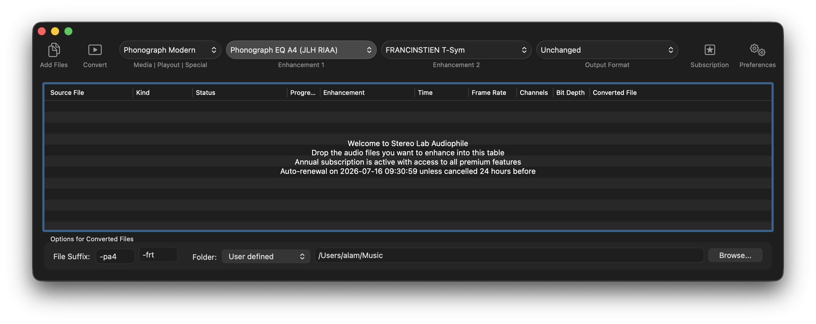
Version 4.3.0 (Audiophile) of the Stereo Lab app' is now available with an important RIAA equalisation option. This version of RIAA is based on work by John Linsley Hood, hence the label JLH-RIAA. To quote Linsley-Hood,
"Although the RIAA replay characteristic suggests an approximately flat velocity response from 20Hz-50Hz, .... the author suspects that this is not done, a constant modulation characteristic being used instead. The author has therefore, for his own use, modified the values of the feedback elements [to accomplish this]." Modular Pre-amplifier Design J. L. Linsley Hood. Wireless World, July 1969.
John Linsley Hood designed many RIAA preamplifiers after this - his first attempt in 1969. His later designs did not include this option, so it's difficult to know if he repudiated this opinion later on. From our point of view (using our ears as the judge), we think Linsley Hood was onto something. A new Afterword will be added to the Needle-drop Handbook to explain this new RIAA equalisation option. A preview is available here or follow the QR code.
Certainly, many mono LPs sound better balanced using this equalisation - an opinion that John Linsley Hood clearly held in 1969 when a susbstantial proportion of his record collection must have included older, mono records.
At any rate it is a useful addition to comprehsive equalisation option available in Stereo Lab.
1/05/2026.
Phædrus Audio are proud to announce the first sales of its PHLUX-DiVA cartridge with its unique integrated tonearm stabilisation technology.
Our first customers report very good results with this radical new technology. Comments range from a "cleaner transient response" (due to the suppression of tonearm resonances), to "improved stereo imagery".
I used the SHUpHLER MkIV with
a wide variety of stereo mic arrays, and
was always able to find a mode that
elevated the sense of spaciousness
and/or enhanced the stereo imaging
precision, without exception.
The PHLUX-DiVA is a new addition to the PHLUX active cartridge range, with unique, integrated tonearm stabilisation technology. The background to this product is given in or blog about tonearm resonance.
We have long harboured an ambition to find a solution to tonearm instability and the PHLUX-DiVA is based on the technology of Dynamic Vibration Absorbers or Tuned Mass Dampers first introduced to tonearm design by Ben Bauer (On the Damping of Phonograph Arms. Bauer, B. JAES July 1963, Volume 11, Number 3). Indeed,
the DiVA in PHLUX-DiVA stands for Dynamic Vibration Absorber.
This technology originated with Den Hartog of Westinghouse Electric nearly a century ago are used in a wide range of real-world applications. They are used to reduce vibrations in bridges caused by moving loads. For example, dynamic vibration absorbers were amongst the measures used to "tame" London's famous Millennium Bridge (the so-called "Wobbly Bridge"). And they are employed in tall buildings & towers to resist wind and earthquake excitations.
The result is an active cartridge that incorporates an electronic stabiliser. The active stabilisation components are powered from the same phantom power source that energises the impedance converter circuitry in the standard PHLUX-II/PHLUX-III cartridge.
1/03/2026. Many readers of the Needle-drop Handbook have constructed the vibration isolation platform described in chapter two, designed by the DJ TJ Hertz. Whilst Hertz's platform offers an enormous improvement in preventing "needle-jump" of the direct-drive decks for which it was designed, it isn't perfect.
Heavy!
To this end, we simulated the performance of a hypothetical improved isolation platform. We assumed a similar platform design, with a similarly damped elastomer suspension, with f0 reduced to 2Hz by increasing the platform mass to 100kg. An isolation platform like this would provide almost 25dB of attenuation at the tonearm resonance frequency, which is wonderful. But 100kg, is an awkward "four-person lift", which renders this design unappealing to all but the most devoted vinylistas - including us!
Double-decker
A more satisfactory approach is a dual-stage platform in which a decoupled table supports a supplementary isolated platform. Several examples of this approach are given in Olson's book Dynamical Analogies*, the most relevant being the proposed support for a sensitive scientific instrument. Without doubt, this is the most practical approach, and a design of this type was developed.
*Dynamical Analogies. Olson, H. F. D. Van Nostrand Company Inc. New York 1943.
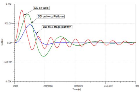
The traces below are simulations of the cartridge signal as a result of shocks as the stylus rests on the record with a direct-drive turntable (Technics SL-1200 Mk. 2) on a solid table; a direct-drive turntable on the Hertz platform; and the turntable on a two-stage platform, inspired by Olson's instrument support.
As so often in engineering, it illustrates that the simple platform makes a significant difference and that a law of diminishing-returns applies. Nevertheless, the advantage of Olson's two-stage platform is real.
The idea is simple: two Hertz platforms are stacked. The upper platform is a pure Hertz design, with suspension with the same characteristics as the Frontenis balls in Hertz' original design. The lower, otherwise identical platform, is supported on very lossy butyl (or Sorbothane †) rubber mounts. The damping of this lower compliance is critical to obtaining the best results, if it too lightly damped, the turntable tends to "wallow" in response to excitation. This assembly is fully tested and works very well.
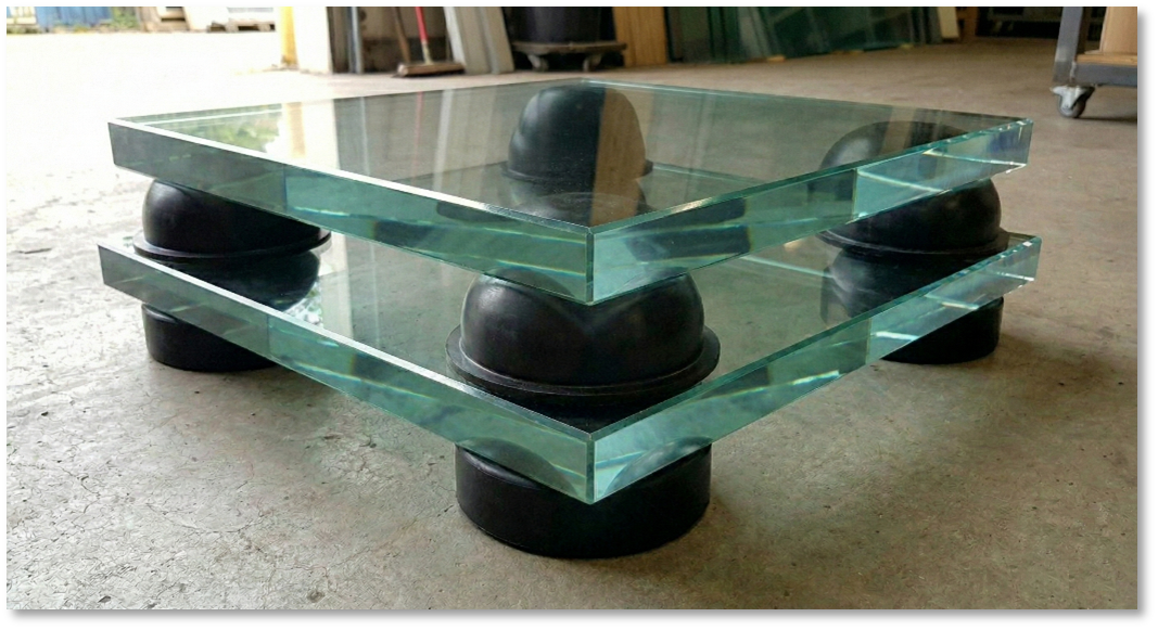
Instead of concrete paving stones in the original design, the platforms are below visualised with glass. This material makes an attractive and practical platform material. A thick pane of tempered glass has a similar density (2400-2600 kg/m3) to concrete (2300 kg/m3).
Four slugs!
The platform does have the disadvantage of being operationally rather low when installed on the floor and too high - and too heavy - to be used on a table. Because each massive platform has a mass (expressed in the old Imperial measure) of 2 slugs, we call this concept the Four Slug Sandwich.**
** A slug = 32 pounds mass.
† Sorbothane is a registered trademark of Sorbothane, Inc.
Version 4.2 of Stereo Lab released
26/01/2026. Pspatial Audio have just released the new version 4.2 of their Stereo Lab app'. This version supports archiving features for recordings on Compact Cassettes.
After the gramophone record, the Compact Cassette is arguably the second-most significant analogue storage-medium for music. Invented by Philips in 1962 as a tape for speech recording for dictation, the cassette gradually improved over the next twenty years. By the mid-1980s, cassette sales surpassed LPs worldwide. The global reach of the format was remarkable. By the 1980s, cassettes were more affordable and durable than records, so in much of the developing world, cassettes became the dominant format — sometimes well into the 21st century.
Especially interesting is Pspatial Audio's Azimuth Dragon, a software version of Nakamichi's NAAC (Nakamichi Auto Azimuth Correction) hardware system. Like its hardware forbear, Azimuth Dragon is capable of correcting automatically for azimuth errors of up to 0.2°.
If you want to read more about cassettes, different tape formulations, even a DIY cassette deck for archiving, there's much more these subjects (and a lot of other things too!) in the new edition of the Needle-drop Handbook due out in early 2026.
14/01/2026. Phædrus ships the first of the new SHUpHLER-IV stereo processor.
The Phædrus Audio SHUpHLER-IV stereo processor offers new and old treatments for stereo microphone and panned-stereo signals. The SHUpHLER-IV builds on the success of the previous SHUpHLERs and adds new processes: the famous Elliptical equaliser due to Neumann as used in the EE66 and EE70 lathe electronics; and the Wavefront Reconstruction Processor (WaRP) that was previously only available in the FRANCINSTIEN WaRP-III processor.
5/01/2026. Forced by acoustical laws to be of significant size, the resurgence of horn loudspeakers in the rarified market of expensive audio equipment is possibly due to the potential they afford for, what sociologists call, conspicuous consumption. The horn loudspeaker affords the opportunity to flaunt lavish traditional materials (polished woods for example), or "high-tech'" materials; concrete, acrylonitrile butadiene styrene (ABS), poly(methyl methacrylate), fibreglass, in a way which outdoes the most extravagant cabinet design for a moving-coil loudspeaker unit.
Few house guests could fail to comment on the Pnoe horn loudspeaker from Arcadian Audio of Athens, (illustrated below) which stand two metres high with a one metre diameter mouth like a pair of fibreglass contra-contrabass saxophones.
Against this, perhaps, cynical view, the die-hard devotees of horn loudspeakers argue that despite their,
....large size, complexity of manufacture and hence high cost...... a small number of enthusiasts .... are unanimous in acclaiming their virtues as loudspeaker enclosures, especially their high degree of realism and "presence".
The quotation is from a short series of articles by Jack Dinsdale, (Horn loudspeaker design. Dinsdale, J. Wireless World March, May, June 1974) which is still considered to be an excellent synthesis of the work on horn loudspeakers, some of it from way back at the beginning of the 20th century. It is required reading if you are seriously interested in the field. Dinsdale works through two example designs which have gone on to have lasting influence on the design of practical horn loudspeakers for home use. Even the Pnoe loudspeakers illustrated above which embody contemporary design aesthetics clearly distant from England of the 1970s, reveal a strong engineering debt to Dinsdale's mini-horn design of fifty years ago (below).
The road less travelled
The horn is the only loudspeaker enclosure to address pretty much all the shortcomings of a moving-coil loudspeaker. It removes the non-linearities due to substantial cone movement; it eliminates voice-coil heating (at least, for the same listening volume); and it damps driver resonance.
The horn is to acoustics what the lever is to mechanics, it matches the drive to the load. Listening to a large horn loudspeaker driven by a simple amplifier of a few watts output power is extraordinary: like watching a bicycle overtake you on the motorway. At the very least, the experience ought to give any open-minded engineer pause for thought.
If you have crewed, or simply watched, a fine sailing ship cutting through the ocean waves at a clip, you will recognise the wistful reflection that perhaps our civilisation chose the wrong path into the brute-force of steam and diesel. The horn is rather like the sail: a fundamentally simple invention which demands understanding. Neither offers the most convenience, and both can betray the careless. Yet both are capable of great refinement and enhancement. Both inventions benefit from, and marry well with, modern materials and technology.
Both lend Nature the opportunity to do the work for us if we give her the opportunity.
15/12/2025. We start with a quotation and something to ponder over Christmas,
Users of phonograph equipment have long recognized that the conventional arrangement of a phonograph pickup at the end of a pivoted arm has a built-in low-frequency stability problem. (A Vibration-Stabilizer System for Phonograph Reproduction. ANDERSON, C.R. JOURNAL OF THE AUDIO ENGINEERING SOCIETY, 1979 APRIL. VOLUME 27, NUMBER 4. )
It's a common observation that, when a stylus is lowered onto a record, it "sinks" slightly as the stylus suspension is compressed. This is due to the stylus compliance which is a measure of the 'springiness' of the suspension. This compliance is a vital component in the reproduction system because it decouples the stylus relative to the cartridge and tonearm. It separates the performance of the dynamic system at sub-audible, and audible frequencies.
For audible signals, we want the cartridge on its tonearm, to "hover" above the groove at a constant height and position. But, as the stylus moves laterally as it follows the volute groove (or up and down due to warps), we want the whole stylus and pickup-arm assembly to move as a unit and consequently produce no electrical output.
The watershed between these two wanted regimes is known as the transition frequency, and we want this transition frequency to be greater than about 7Hz, so that signals are not obtained from ripples and warps. Yet, the frequency should be less than about 20Hz to permit a flat frequency response down to the lowest musical notes. This doesn't give us a lot of wiggle-room, so the matching of the arm moment of inertia to the compliance of the stylus suspension needs to be done with care.
More commonly this transition frequency is known as the arm resonance frequency (f0), because of an unfortunate consequence of these two physical components. For all the good the stylus compliance does, it undoes at the frequency where the compliance resonates with the rotational moment of inertia of the tonearm. Just as a weight hanging from a spring has a natural resonance frequency, so do the compliance of the stylus assembly and the effective mass of the pickup-arm assembly. The frequency of this resonance (f0) is calculated as,
Where M is the effective mass of the of the tonearm as seen at the stylus tip (in either grams or kilograms) and C is the compliance of the stylus suspension (in either cm/dyne or m/N). Frequency f0 is in Hertz. Test records exist to excite this resonance and it's often the case that the frequency response rises easily by 10dB or more at this frequency.
This is often considered as the only significant effect of tonearm resonance, but, in truth, it is the least significant. We can reduce the low frequency shudder introduced by the tonearm resonance by high-pass filtering and vertical low-frequency noise elimination - especially if we use sophisticated digital techniques as in the Stereo Lab app'. However, there are two further effects - each less obvious and less well appreciated, but both highly detrimental. Worse still, they defy electronic or algorithmic elimination. The only realistic solutions to this effect are mechanical and we must hand the problem back to the mechanical designer.
Downforce modulation
The first poorly recognised consequence of tonearm resonance is that, at the arm/cartridge resonant frequency, significant vertical acceleration of the tonearm occurs. The force required to accelerate the arm mass is, inevitably, drawn from the stylus-groove interaction, causing large fluctuations in instantaneous tracking force. If these fluctuations reduce - or exceed - the nominal tracking force, the result is mistracking and unnecessary groove wear.
Let's imagine a - very typical - example of a pickup with a compliance of the pickup of 12.5 × 10⁻⁶ cm/dyne, and an effective tonearm mass of 20g, tracking with 2.0 grams of stylus force. We note that the headshell is seen bouncing with a peak amplitude of 0.1mm. We can calculate that the arm/cartridge resonance is 10Hz. For a peak vertical excursion A = 0.1mm, and a peak acceleration of (2pf0)², the force involved (F = ma) = 0.008N, equivalent to 0.8 g of tracking force.
This force alternately adds to and subtracts from the static stylus load. So, at the top of the movement, the tracking force reduces to 1.2g - enough to cause mistracking, and at the bottom of the motion it increases to 2.8g - enough to increase groove wear.
Scrub flutter
The second consequence is that the motion of the tonearm causes the stylus to "scrub" backwards and forwards from a mean position in the groove. This effect was analysed by Anderson (reference above) and results in a frequency modulation (flutter) effect of astonishing magnitude. In a typical setup, frequency modulation depth can reach as high as ±2%. This is a shocking figure. The acceptable limit for wow & flutter (NAB standard) from the turntable itself is ±0.14% peak.
What can we do about tonearm resonance?
We hope to have some good news about this in the New Year.
8/12/2025. Although we think of the 33⅓ RPM discs as being introduced in 1948, this was only true of the introduction to the public. Discs spinning at 33⅓ RPM pre-dated the commercial LP by twenty years. The 33⅓ RPM speed was originally chosen increase the playing time of shellac records for synchronised audio in the cinema where the system was known as Vitaphone; the first commercially successful apparatus for the "talkies".
Using a disc nearly 16 inches (about 40 cm) in diameter and rotating at 33⅓ RPM, the playing time of one side of a record was increased to 11 minutes which matched the running time of 1000 ft. of film at 90 ft./min (24 frames/s).
Although the Vitaphone system had been overtaken by sound-on-film systems by the mid-thirties in the cinema, the format of the 16 inch, 33⅓ disc was retained in radio broadcasting by the networks who needed a standard format to distribute programmes to affiliated, local stations.
To play these broadcast transcription discs, we need a tonearm longer than the almost standard nine-inch (230mm) type. Twelve-inch (305mm) tonearms were standard in broadcasting; in order that 16" discs could be played, and broadcast players existed right up to the 1960s to contend with these discs.
But what of vinylistas who insist longer tonearms are beneficial — even if we play only 12-inch LPs?
They argue that lateral tracking error is less with a longer arm, so distortion must be commensurately lower too.
There is some truth in this. After all, an infinitely long tonearm would have zero tracking error. But, if we do the maths, as the arm length is increased beyond seven inches (178mm) which is the minimum dimension of a practical tonearm to play LPs, a law of diminishing returns exists. Little practical benefit is gained by an increase over 9 inches (230mm). Indeed, the appreciation of this fact is the grain around which the standard nine-inch tonearm design crystallised. (The maximum angle error in a correctly aligned nine-inch (230mm) tonearm is 2.33° and that due to a 12-inch tonearm 1.75°. This translates to a theoretical improvement in distortion from 0.74% to 0.54%.)
A further advantage is claimed for the longer tonearm. The optimum crank (offset)angle in a nine-inch tonearm is about 23°, whereas the optimum for the longer type is about 17°. Side-thrust (or skating force) is proportional to the tangent of the tonearm offset angle, so the required anti-skating force is reduced by about 26%.† Whilst this is useful, it doesn't eradicate the need for side-thrust compensation. The tone arm design isn't thereby simplified, and the asserted advantage is largely illusory.
†Tan 23° = 0.42; and tan 17° = 0.31
Against these fragile arguments looms the major disadvantage the longer tonearm: it is heavier. Given that the moment of inertia of a thin rod of length L and mass m, perpendicular to the axis of rotation, rotating about one end (as illustrated left) is given by the expression, ⅓mL2 , it will be appreciated that to manufacture a 12-inch arm with the equivalent inertia of a 9-inch version, the weight of the arm would have to be about one half of the latter. (This is based on the calculation that (12/9)2 = 1.78.)
The case for a longer tonearm turns on the argument that an increase in the mass moment of inertia is justified by a small reduction in theoretical distortion. It's a tenuous argument unless ‐ of course ‐ you need to be able to play 16-inch transcription recordings.
1/12/2025. Let's start with a simple maxim: power amplifiers must not be driven into overload. Even the advocates for the argument that all amplifiers sound the same are quick to point out that the minimum requirement is that "overload precautions have been observed."
Could this be the missing x-factor in our assessment of power amplifiers and why so many critical listeners claim to be able to hear differences between amplifiers when scientific testing proves they sound the same? Are we inadvertently operating our power amplifiers with inadequate headroom?
We conducted the following experiment* to determine the degree of clipping we might be able to tolerate before declaring the onset of obvious distortion. We prepared examples of tones and music with peaks extending to 0dBFS. We then manipulated the data mathematically to clip all values above various thresholds. The illustration below is an example of the multitrack session in the DAW. Track #1 is of the original audio, track #2 was the value-limited version. Note, track #2 was not produced by dynamic limiting with time constants: this was brutal clipping of all values above a certain level.
Astonishingly, we were able to clip the signal to a remarkable degree before it was obvious that we were doing so. With clipping set at -5dBFS (which means all audio values above 60% amplitude were trimmed), identifying the effect was uncertain.
If the original and the clipped version were directly compared (by soloing the appropriate tracks), the differences were abundantly clear. But, without reference to the non-clipped version (which is always unavailable when listening to an amplifier in isolation) the effect of the overloading was not obviously apparent. Only once the threshold level was reduced to -10dBFS (meaning all data above 32% amplitude were trimmed), was the distortion immediately identifiable as overloading.
In short, it does seem possible that many of us are operating our amplifiers with
insufficient headroom and thereby, unknowingly, distorting what we hear and
misrepresenting the audio signals on which we are working.
Because different amplifiers overload at different levels, we infer that it might account for the observed
differences between different units when casual comparisons are made.
Power monitoring
Is "amplifier sound" due to unintended amplifier clipping? It's a reasonable conjecture, but it would seem very difficult to prove.
*This is unofficial, the listening group was tiny and the correct experimental protocols
for perceptual experiments weren't followed. There is also the issue that practical power amplifiers
may not clip as "cleanly" as this mathematical manipulation. The results are therefore only interesting
for general discussion.
24/11/2025. We had our attention drawn to some "radical and new" damping products. The products offer particle damping, which is said to provide "more efficient and wide frequency-range vibration absorption than previous solutions."
Particle dampers are devices that work by a combination of impact and friction damping. They dissipate the energy of a system by transferring it to a bed of particles. This bed is geometrically constrained to remain inside a container fixed to the vibrating system. As such, the motion-caused interaction occurring inside the container damps the absorbed energy. Particle damping emerged in the 1960s aerospace industry when engineers sought damping methods that could survive space vacuum and extreme temperatures, in which lubricants dry out, fluids boil off, and elastomers degrade under vacuum or temperature extremes.
Does particle damping have audio applications?
Particle dampers do provide broadband damping, and prima facie, this quality is welcome in audio equipment. However, particle damping provides amplitude-dependent damping. It is highly nonlinear. The damping effect of particle dampers depends on significant amplitude of vibration, and significant acceleration — to make particles move. Particle damping is good at controlling large, transient vibrations (e.g. shock, impacts). But, at small amplitudes, particles may not move at all, or only "slosh" around slightly. The energy dissipated is thereby, negligible.
In audio equipment, vibrations are typically: very small in amplitude (microns or less); and low in acceleration. These vibrations are not enough to mobilise the particles. And, if the particles aren't mobilised, the damper does nothing. This creates a serious mismatch for this technology in the context of damping vibrations in audio equipment. It is likely to offer far less damping than constrained-layer damping, viscoelastic damping, or even well-designed mechanical isolation.
In electrical analogy terms (see afterword five of the Needle-drop Handbook), the particle damper is modelled as a resistor in series with back-to-back Zener diodes. The damping effect is only useable above a certain amplitude of forcing function. This is the opposite of the behaviour we seek in keeping small vibrations from affecting — for example — a turntable. In theory and in practice, particle damping is ineffective or impractical at small amplitudes, such as the vibrations which trouble audio equipment.
17/11/2025. First shipment of new Microline version of PHLUX-III active cartridge.
Originally a special customer request, we are now able to supply the PHLUX-III cartridge with: a 3µm × 56µm, nude, square shank, Microline stylus. This complements the choice of: a 6.5µm × 68µm nude, square-shank, Shibata stylus; 76µm conical stylus, for 78RPM archive work; and a 18µm conical stereo cartridge for (low-wear) LP work. The cost of the new PHLUX-III with Microline stylus is the same as for the Shibata stylus version.
The Groove Sleuth SOLUTION acts as an RIAA preamplifier for moving-coil, moving-magnet, and PHLUX active cartridge types, whilst simultaneously providing a computer soundcard with a non-equalised output for software processing.
The GS-SOLUTION also functions as an adaptor for PHLUX active and moving-coil cartridges, so that they may feed a standard moving-magnet level phono input. All the various functions are selected by means of small "piano" switches on the unit.
1/11/2025. Phædrus Audio are collaborating with software company Pspatial Audio to develop a new active tape head for archiving precious cassette tapes.
The signals derived from the replay head from a cassette tape running at low speed with a tiny magnetic gap are very small indeed. The maximum recoverable signal is in the region of 1mV RMS. Tape noise floor is about 50dB to 56dB below maximum signal level (depending on tape type and head material), so we can reason that the input-referred electrical noise of the head-preamplifier system must be at least 60dB below the head signal (1µV RMS) and preferably 70dB below (0.316µV RMS). In terms of the phono preamplifiers we examined earlier in this book, we may consider the tape head transducer as a very insensitive moving coil phono cartridge with the impedance of a moving-magnet type ‐ a tricky combination!
We saw an exactly analogous situation in the design of moving magnet phono preamplifiers. Our reaction was the development of the PHLUX active cartridges. We applied the same technique here. We engineered a tiny, phantom-powered buffering amplifier which we installed immediately behind the tape head. The signal from this buffer feeds the signal to the tape preamplifier at low impedance.


 I used the SHUpHLER MkIV with
a wide variety of stereo mic arrays, and
was always able to find a mode that
elevated the sense of spaciousness
and/or enhanced the stereo imaging
precision, without exception.
I used the SHUpHLER MkIV with
a wide variety of stereo mic arrays, and
was always able to find a mode that
elevated the sense of spaciousness
and/or enhanced the stereo imaging
precision, without exception.


 Against these fragile arguments looms the major disadvantage the longer tonearm: it is heavier. Given that the moment of inertia of a thin rod of length L and mass m, perpendicular to the axis of rotation, rotating about one end (as illustrated left) is given by the expression, ⅓mL2 , it will be appreciated that to manufacture a 12-inch arm with the equivalent inertia of a 9-inch version, the weight of the arm would have to be about one half of the latter. (This is based on the calculation that (12/9)2 = 1.78.)


 The signals derived from the replay head from a cassette tape running at low speed with a tiny magnetic gap are very small indeed. The maximum recoverable signal is in the region of 1mV RMS. Tape noise floor is about 50dB to 56dB below maximum signal level (depending on tape type and head material), so we can reason that the input-referred electrical noise of the head-preamplifier system must be at least 60dB below the head signal (1µV RMS) and preferably 70dB below (0.316µV RMS). In terms of the phono preamplifiers we examined earlier in this book, we may consider the tape head transducer as a very insensitive moving coil phono cartridge with the impedance of a moving-magnet type ‐ a tricky combination!