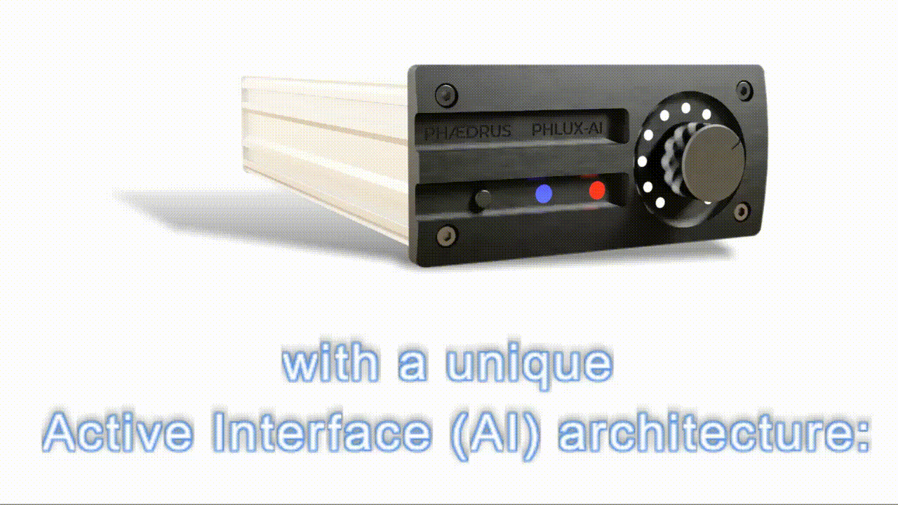
Phćdrus Audio's PHLUX-AI high-quality preamplifier is unique: it is designed for all vinylistas – both the hard-line analogue lover and the modernist.
The PHLUX-AI preamplifier functions as a no-compromise, high-quality stand-alone phono preamplifier, or works in conjunction with Pspatial Audio’s Stereo Lab app’ which runs under OS X on the Apple Mac.
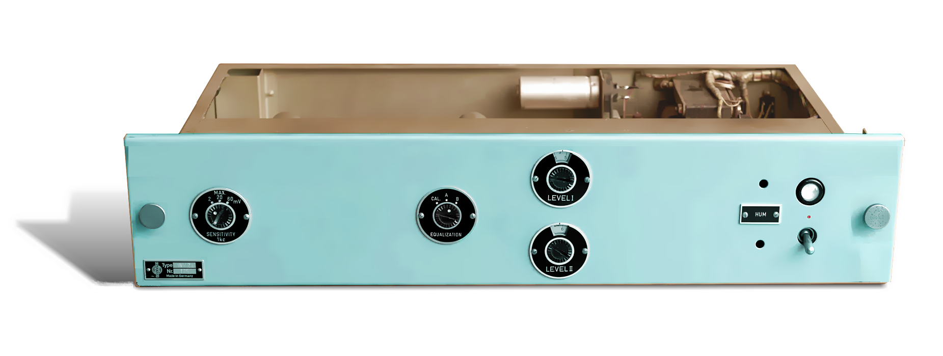
 For the analogue purist, the PHLUX-AI preamplifier is designed to offer state-of-the-art, low-noise preamplification in a unique, and innovative bridge-based preamplifier configuration. It also employs circuit techniques from the summits of analogue design (for example, the legendary WV2 preamplifier from Neumann).
For the modernist (and the archivist), using the Stereo Lab app’ you may apply the most powerful technology of our age – modern computing – to recovering the best possible signal quality from a record. For example, phase-linear warp and rumble filtering is only possible in the digital domain and reveals a bottom octave with unprecedented clarity and realism. The accuracy of RIAA equalisation and perfect channel balance in software ensures an uncoloured sound with superb stereo sound staging. And the flexibility in recording characteristics and intelligent noise-reduction will bring to life records you thought mediocre. Moreover, Stereo Lab also includes software decoders for CD-4, QS and SQ quadraphonic and Ambisonic LPs; thereby bringing life to forgotten, analogue, multichannel gems.

Our tests have revealed that the PHLUX-AI is the first really innovative phono preamplifier in a generation!
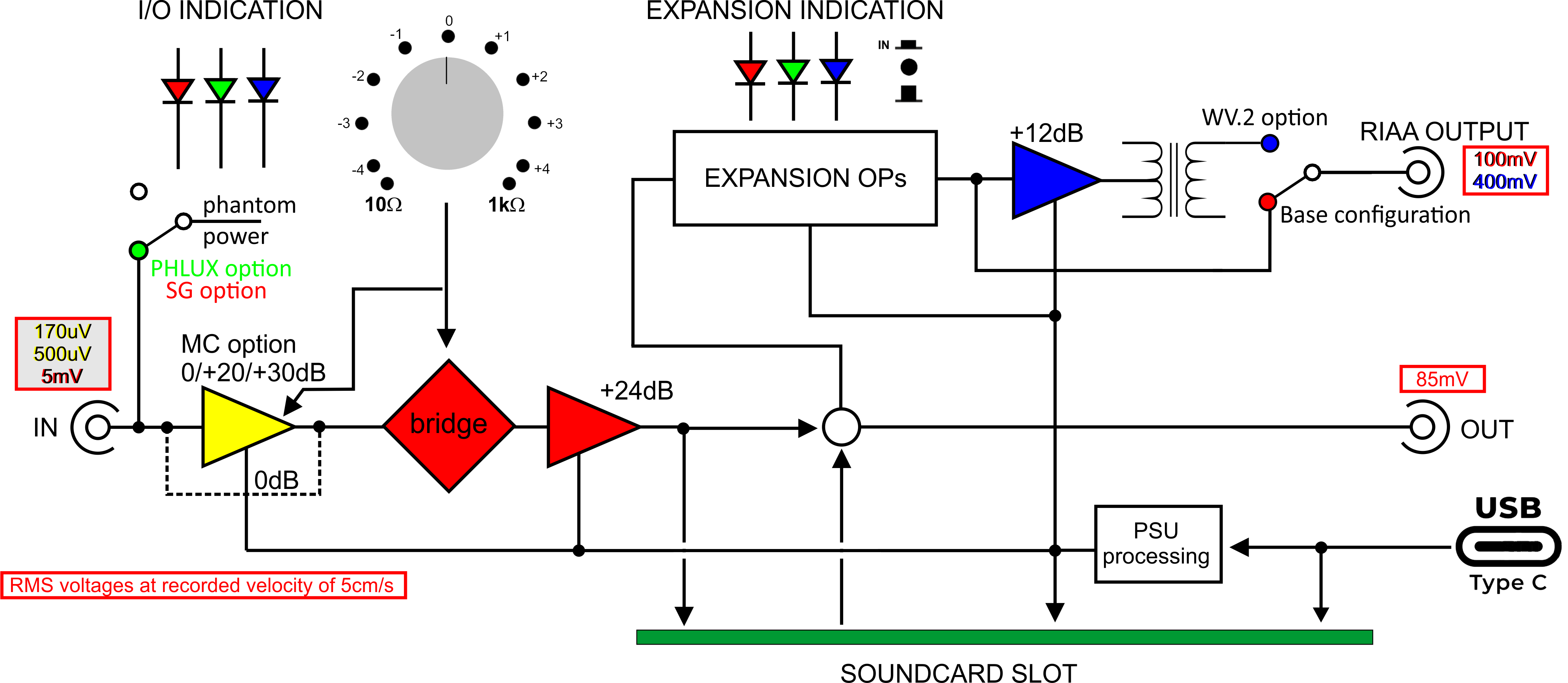
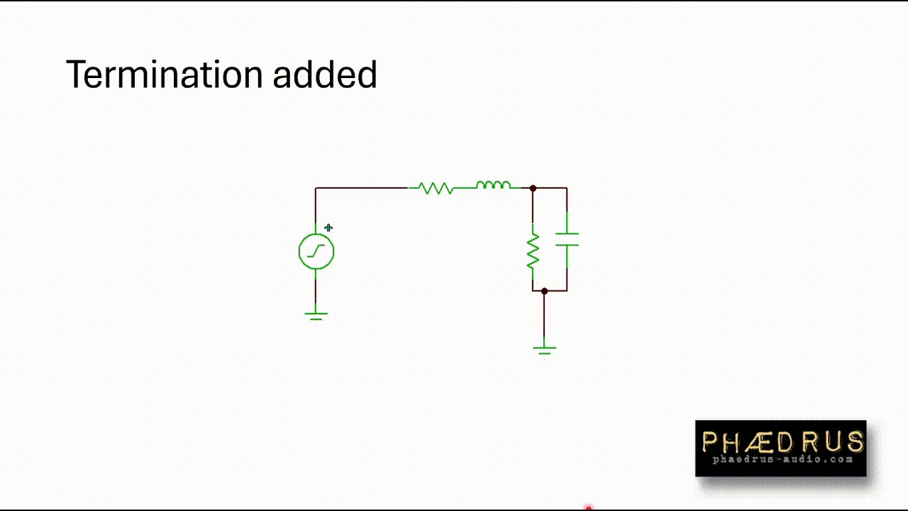
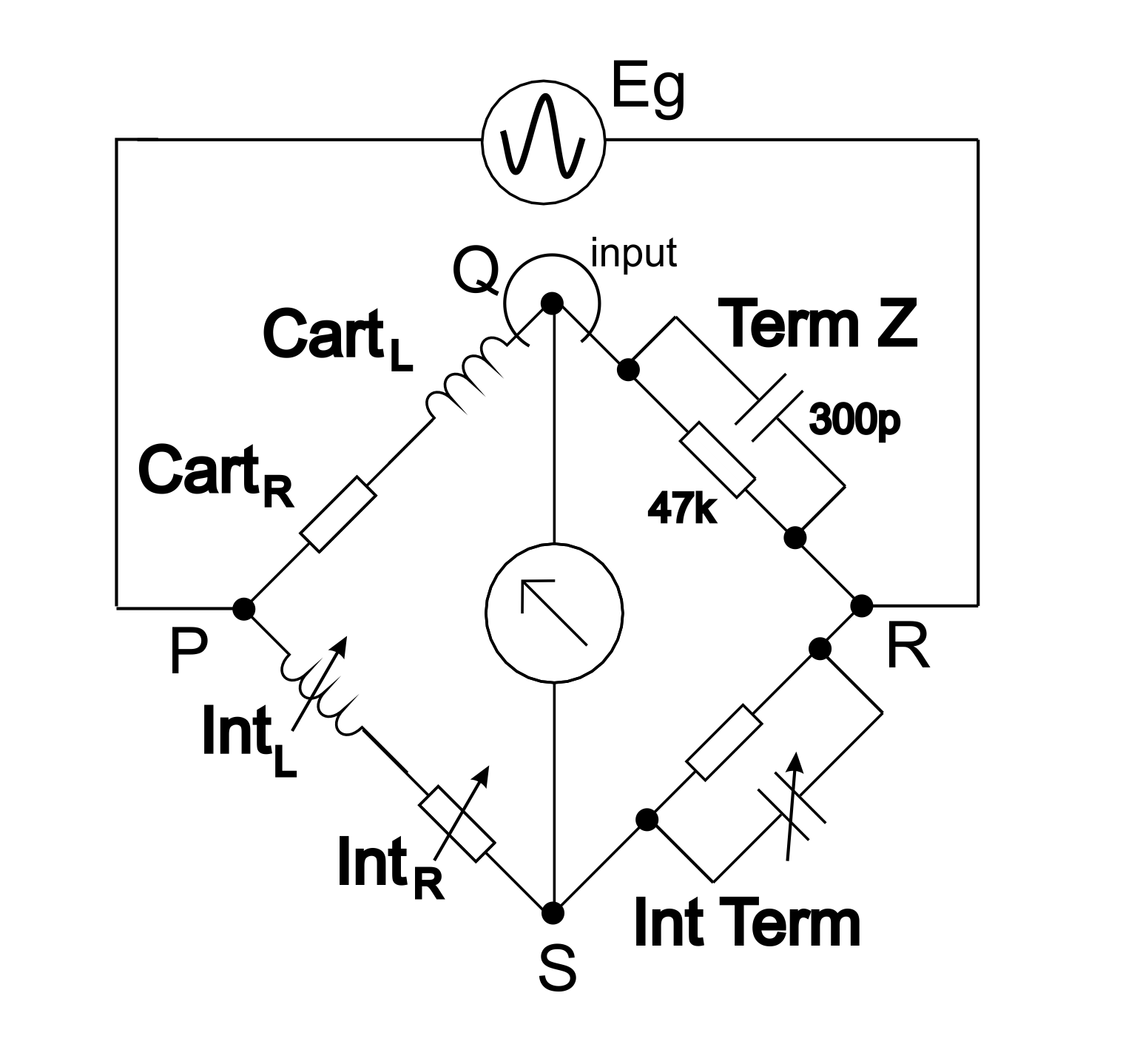 The PHLUX-AI operates as a Maxwell bridge which compensates for the complex cartridge impedance and the complex impedance of the connecting cable and termination with complex impedances inside the PHLUX-AI unit.
A Maxwell bridge is a modification of the Wheatstone bridge. It is named after James Clerk Maxwell, who first described it in 1873.
See the PHLUX-AI manual for a detailed description of the bridge-based architecture as well as instructions on switch selection and cartridge compatibility.
We wanted the advantages of the PHLUX cartridge, but we have a policy to use Shure V15 cartridge for archiving. With the PHLUX-AI we get the low-noise, level and extended bandwidth of the PHLUX cartridge using our precious Shure cartridges in our preferred headshells....
The functionality of equipment like the PHLUX-AI preamplifier is often most rapidly grasped with a facilities diagram, like the one given below.
In order to see the multiple ways the PHLUX-AI may be employed, we present five user cases: the (Home) Archivist; the Pro Archivist; the Audiophile; the Record Collector; and Mr. Zane Gauge.

See the PHLUX-AI manual for a detailed description of each of these users and their equipment set-up.
In this section we have a demonstration of the PHLUX-AI, compared with a standard RIAA preamplifier using a moving magnet cartridge.
Here's the results from the moving-magnet cartridge coupled with a standard RIAA preamplifier.
And here's the PHLUX-AI interfacing the same cartridge with valve-based Neumann WV2 RIAA stage.
This section is βeta. It does not work in all browsers.
Here, the same two files as in the example above are arranged to play simultaneously. A button ("Toggle") enables you to switch between the two recordings; enabling you to A/B compare the MM cartridge via a normal interface with the Phædrus Audio PHLUX-Active Interface.
Track 1 is the PHLUX-AI
Track 2 MM via standard interface.
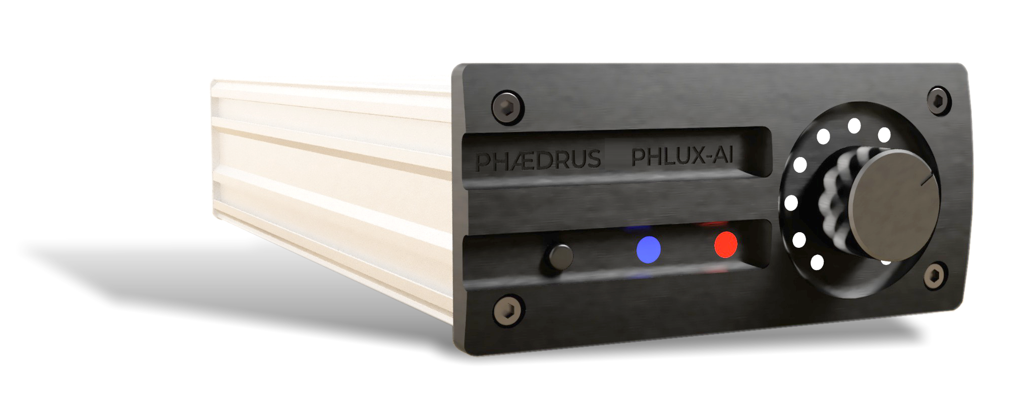
The function of the single front-panel control knob varies according to the input option fitted. In the case of the moving-magnet input stage, the control knob adjusts the bridge-balance. This is set various ways as explained in the PHLUX-AI manual.
When the moving-coil input stage is fitted, the control knob adjusts the loading presented to the cartridge, which gives subtle voicing shifts.
In the case of the PHLUX input option, and when the strain-gauge input option is present, the control is a fine level-control.
In the case of the preamplifier option, the control acts as a high-quality (full range) volume control.
The left-hand front panel multicolour indicator indicates the input and output (I/O) options fitted in the PHLUX-AI preamplifier. When a SYNOPSIS soundcard is fitted, the LED continues to indicate the input configuration, but when valid audio data is passed over the USB interface, the indicator illuminates WHITE.
Other expansion options: PHOENIX shellac processing; FRANCINSTIEN stereo correction; etc. are indicated by the right-hand multicolour LED configuration indicator.
Today, USB power – usually presented via a USB Type-A connector – is ubiquitous. It is available, either via the computer hosting the DAW, or via stand-alone plug top power supplies.
USB power is not known for its stability or lack of noise. To that end, the PHLUX-AI preamplifier incorporates advanced power supply processing which filters any power supply noise and thereby achieves the excellent noise and dynamic range figures it does (see Specifications below).
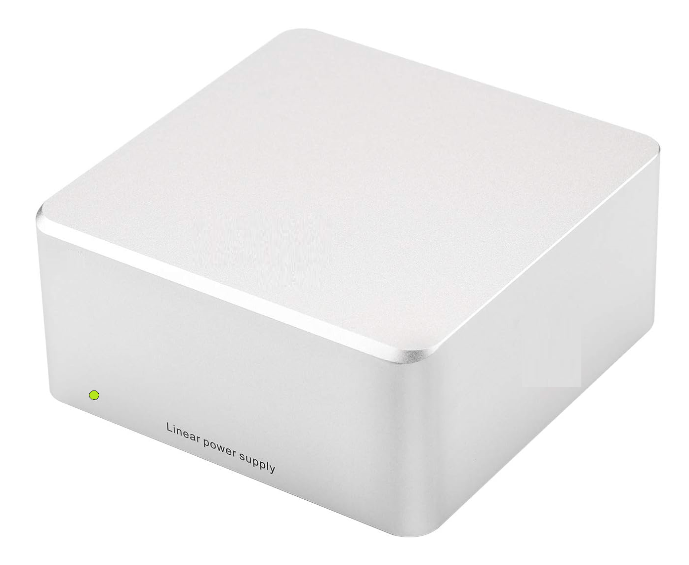
Some customers may wish to use an external, linear power supply type (especially when not using the internal SYNOPSIS soundcard). There are several manufacturers of this type of supply, and they deliver high-quality and low noise 5V DC at very reasonable cost.
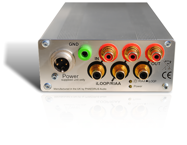
Full, technical specifications are given in the PHLUX-AI manual.
Phćdrus Audio reserves the right to change specifications without notice.

Address all mail to sales@phaedrus-audio.com