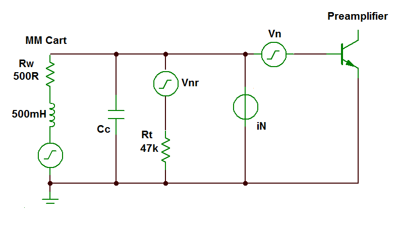
 The circuit illustrated (right) is a standard input circuit for a moving-magnet phono preamplifier - the Groove Sleuth II included. The moving-magnet cartridge is inductive because it is made of fixed coils of many, many turns of fine wire.

The technique sets a new standard for low-noise phono preamplification and increases digital resolution of needle-drops by nearly three bits.5
Click image (left) to see a video.
Input cooling is a new option for the Groove Sleuth Mk.II preamplifier.
Phono preamplifiers (when meaningful specifications are published at all) are normally specified with a noise performance measured by short-circuiting the input of the device. Consumer reviews follow this methodology. This technique gives results which do not correlate with real-world performance.
 The circuit illustrated (right) is a standard input circuit for a moving-magnet phono preamplifier - the Groove Sleuth II included. The moving-magnet cartridge is inductive because it is made of fixed coils of many, many turns of fine wire.
Thermally induced Johnson noise is only generated in the real, resistive part of the source impedance (Rw): no thermal noise is generated in the inductive part of this impedance.
However, the reactance of the inductance L decouples the low resistance value of the winding (typically around 500Ω) from the termination resistance (Rt, 47kΩ) as frequency increases. (See note 3 for a more detailed analysis of this network and the source of noise due to Rt).
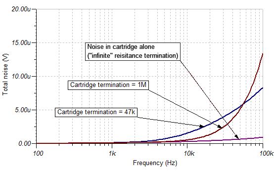
So, the noise from the network of cartridge and termination resistance is dominated at high frequencies, not by the 500Ω, but by Rt with a value one hundred times greater. A graph of the noise generated in Rw alone and in the full circuit is illustrated below. There's quite a difference.
Is there any way that we can compensate for this extra thermal noise in Rt?
Yes there is, we can remove it, or replace it with a much higher resistance, say ten or twenty times as big: see the line of the graph which illustrates the total RMS noise when the 47kΩ is replaced by a 1MΩ. To 10kHz at least, there is no extra noise created above the basic thermal noise of the cartridge.
Well, that was easy!
Not so fast..... The problem is that the cartridge requires a termination impedance of around 47kΩ to keep its frequency response under control and damp the effect of the resonance caused by the cable capacitance interacting with the inductive source. The damping resitance for this resonant circuit Rt has standardised over the years to a value 47kΩ.
What we need is a 47kΩ resistor, to damp the resonance, but cooled to near absolute zero so that all the electrons stop rushing around in a random fashion and creating noise.
".... What we need is a 47kΩ resistor, to damp the resonance, but cooled to near absolute zero so that all the electrons stop rushing around in a random fashion and creating noise."
The random, thermally generated noise in any resistance R is given by this equation,
Vn = √ [ 4 k T B R] RMS volts ............... (equation A)
where k is Boltzmann’s gas constant (1.38 x 10⁻²³ joules/ degree Kelvin), where T is absolute temperature in degrees Kelvin (K = °C + 273), B is bandwidth in Hz of the measuring set-up.
It's quite possible to accomplish a noiseless 47kΩ (Rt) resistance by arranging for it to be submerged in liquid nitrogen - or some other liquid gas. Doing so reduces the T in equation A — and thereby the entire equation — to near zero. That's quite a party trick! But it isn't a very practical long-term solution for a desktop preamplifier.
Fortunately, there is a way to do this electronically. The technique was developed by W.S. Percival¹ of the EMI Research Laboratories whilst he was working on television and RADAR technology with the famous Alan Blumlein just prior to the outbreak of the Second World-War in Europe. In Percival's own words,
".... the effect of the terminating resistance is to reduce the signal to noise ratio ..... If the signal is very weak this may be of some importance." Percival asks the rhetorical question,
".... Can a valve [vacuum tube] be so connected as to act .... as a refrigerating device? "
He proves, theoretically and experimentally that indeed it can. The technique has same influence on the thermal noise generated in the termination resistor as cooling it down to a lower absolute temperature.¹ The lowest effective temperature Percival attained with this circuit was 116°K.
Percival's idea appears to have been first applied to phono cartridges by a team in Belgium - although it took forty years for it to be so applied and by that time vinyl was in its dying days as a mainstream medium.² In the case of the advanced technique as applied in the Groove Sleuth Mk.II preamplifier, the resistor is "cooled" to within 9° of absolute zero.
But what of current noise generator (iN) which is part of the preamplifier? That noise current flows in the increasing impedance of the cartridge and - once again - causes increased noise at high-frequencies. Now that we've "cooled" Rt, is there anything we can do about iN flowing in the cartridge impedance?

Yes there is. The noise generator in a low-noise bipolar preamplifier (like the one we use in the Groove Sleuth) is due to shot-noise† on the bias current of the bipolar input transistor(s). Appendix 1 covers the noise mechanisms in a bipolar junction transistor.
† Shot-noise arises from the fact that any electric current is not completely smooth and continuous but is the sum of numerous small pulses caused by the passage within the device of discrete electrons.
Vacuum tubes (valves) and FETs do not suffer from this type of current noise because they are electrostatically operated and operate with almost no bias current at all.
However, whilst tubes and FETs virtually eliminate the noise generator iN, most suffer from much higher voltage noise generators (Vn). The good these exotic devices do in relieving us of current noise, they often squander in dishing up more voltage noise.4
The key to voltage noise is the device transconductance (or mutual conductance gm). This is true of bipolar junction transistors, FETS and valves.
The equivalent (voltage) noise in the input circuit of a tube operated as a triode is given by the equation,
= √[ 4 k T B (2.5/gm) ] RMS volts
Simply put (compare with equation A), this equation represents the electrical noise generated by a resistance 2.5/gm in the grid circuit.7 (Compare this with the equivalent equation for a bipolar transistor in Appendix 1.)
 In a FET, the equivalent equation is,
= √[ 4 k T B (0.67/gm) ] RMS volts
Thus equivalent to the noise generated by a resistance (0.67/gm) in the gate circuit. (Once again, compare this with the equivalent equation for a bipolar transistor in Appendix 1.)
High transconductance vacuum tubes may be sought out - even today. The record is probably still held by the EC8020 manufactured by Telefunken in the 1960s with an amazing transconductance of 60mA/V.
For a while we considered a vacuum-tube front-end for the Groove Sleuth Mk. II preamplifier despite the amusing irony that two hot extra components would be added as part of "cooling" the termination resistance option.
But there wasn't the room, nor the power-budget for two triodes. Besides, high transconductance FETs are much easier to find, don't require a DC heater supply, and have a guaranteed flicker-noise performance, which triodes don't have (see Appendix 2).
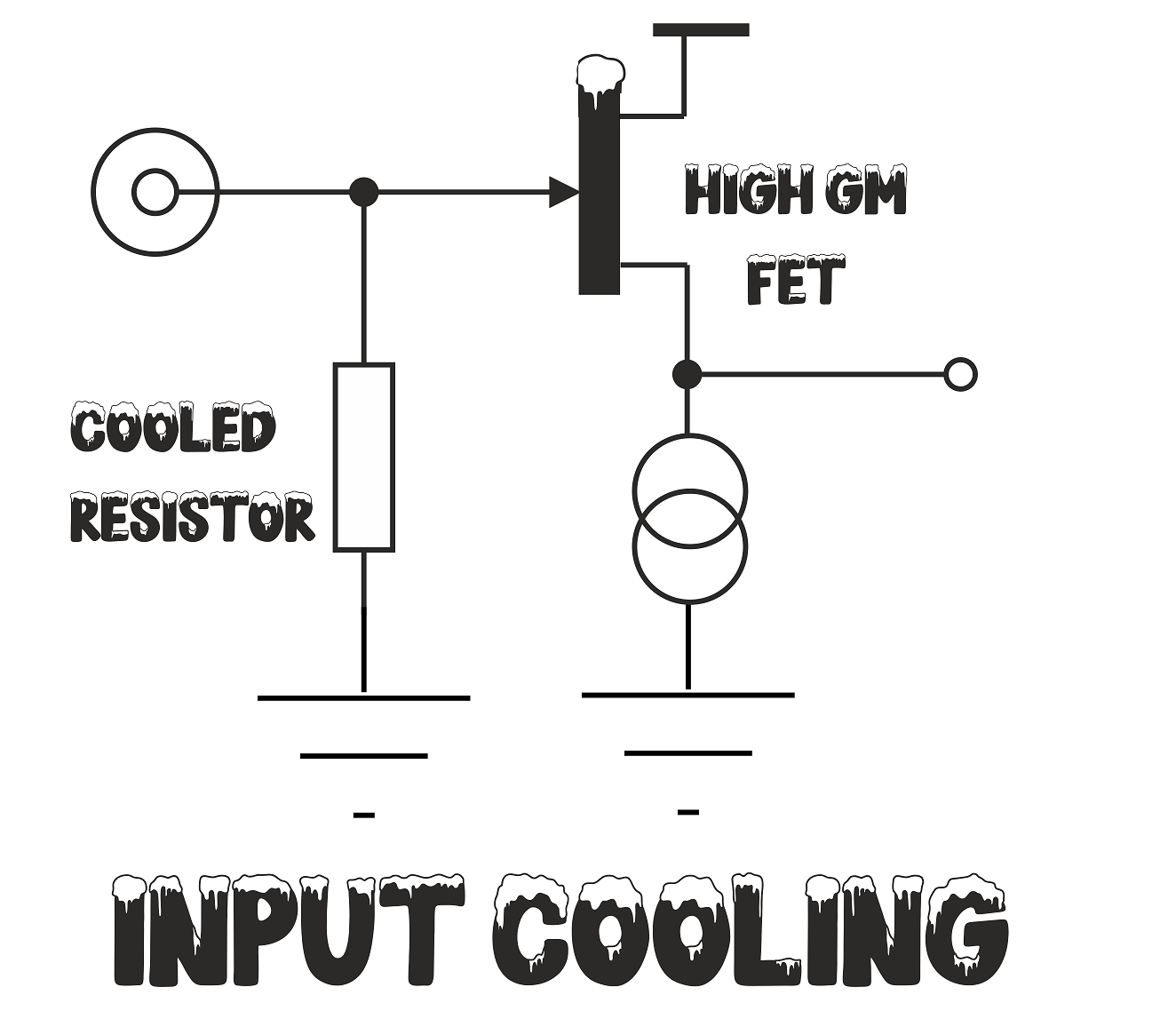
So, in the end, we opted for a very high transconductance FET buffer prior to the preamplifier as illustrated.
With this configuration we are able to reduce the combined noise in the termination resistance (by electronic cooling) and noise due to the preamplifier iN by 17dB when operating a standard moving-magnet cartridge.5 That's equivalent to nearly three bits of extra digital resolution!6
Another way to express this is that the noise-figure of the preamplifier is reduced from 19dB to just 2dB.
".... we are able to reduce the combined noise in the termination resistance (by electronic cooling) and noise due to the preamplifier iN by 17dB when operating a standard moving-magnet cartridge..... That's equivalent to nearly three bits of extra digital resolution!"
The electronic cooling technique isn't just relevant to moving-magnet cartridges.
When moving-coil cartridges are used with step-up transformers like the Phædrus Audio TRANSFORMER product, the source impedance, once again, rises with frequency and electronic cooling helps here to increase the available dynamic range. The effect is not as marked as with a moving-magnet cartridge, but input-cooling reliably adds an extra bit (6dB) of digital resolution.
 Input cooling is not incompatible with the PHLUX-II active phono cartridge but many of the problems input cooling addresses are similarly addressed by isolating the cartridge inductance (L) from the cable capacitance (Cc) which is at the heart of the PHLUX-II design.
We therefore do not recommend input cooling option if you choose to use the PHLUX-II active phono cartridge. The money is better spent on our of our new, advanced stylus profiles.
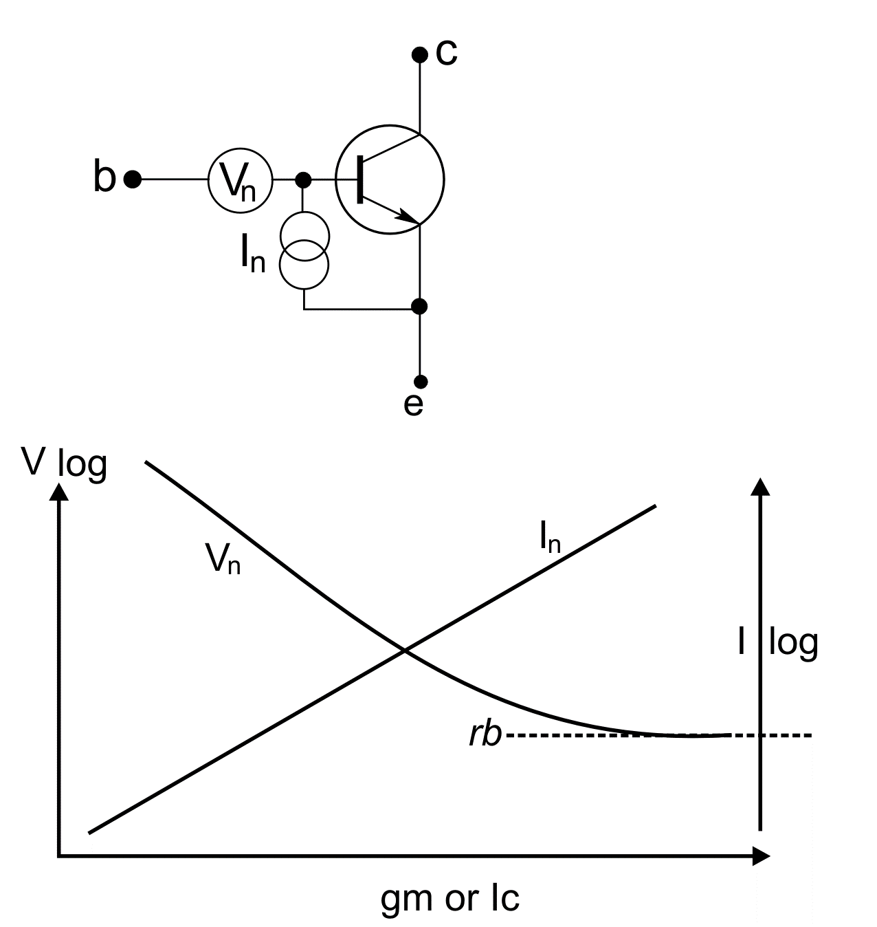
Noise in a bipolar junction transistor may be modelled by the addition of noise generators added to a theoretically perfect, noiseless transistor as illustrated.
Vn has the RMS value of:
Vn = √ [ 4 k T B (rbb + 1/(2.gm)] RMS volts
where k is Boltzmann’s constant (1.38 x 10⁻²³ joules/ degree Kelvin), where T is absolute temperature in degrees Kelvin (K = °C + 273), B is bandwidth in Hz, and rbb is the extrinsic base resistance of the transistor. Mutual conductance (gm) is in amps per volt. Remember, in a transistor, gm is given by 40mA/V per mA of collector current.)
We can see that the noise voltage-source is that of the extrinsic base resistance (rbb), which is the standard expression for thermal agitation noise in a resistor, plus another term which is inversely proportional to gm. In fact, it’s possible to see Vn as effectively the result of two resistors in series: one with the value of rbb (the extrinsic base resistance) and the second with the value 1/(2.gm) or 0.5/gm. (It's interesting to compare this last equation with the equivalent expressions for a FET and for a vacuum-tube, see the main text.)
The current-generator noise source in a transistor (In) is due to shot-noise on the static bias current and has the RMS value of:
In = √ [2qIdcB]
where: q = electronic charge = 1.60 X 10⁻¹⁹ coulomb, Idc is is the mean value of the current in amps and B is bandwidth in Hz.
This equation is excellent in that it reminds us that shot-noise arises from the fact that any electric current is the sum of numerous small pulses caused by the passage within the device of discrete electrons. However, it isn't in a form in which we may easily compare it with the voltage noise generator. Baxandall8 manipulated the equation into the the much more useful form,
In = √ [4kTB ÷(2β/gm)]
where β is the current-gain of the transistor.
From which we can see that the current-noise generator is directly proportional to gm (because gm is proportional to collector current and thereby to bias-current) and indirectly proportional to β. The latter because, the higher the current gain of the transistor, the lower the bias-current for a given gm.
We can sketch what will happen to Vn and In as the value of gm changes (which is the same thing as saying, as collector-current changes). Note that the axes of the graph are log/log. As the curves illustrate, In goes on climbing with increasing transconductance (gm) and Vn reduces to an asymptotic limit defined by rbb - a parameter frustratingly almost never given in device datasheets!
The choice of the "best" device for lowest noise depends on the resistance (or impedance) of the source of the signal. In the case of a bipolar junction transistor amplifier, if the source impedance is high, then the noise current generated by the current noise generator must be made small — because the this signal will flow though through the large impedance and generate voltage noise-signal at the transistor’s base. One option may be to operate the transistor at low current but this may destroy high-frequency response. A better option will probably be to consider a FET or even a vacuum tube.
If the source resistance is low, then the magnitude of the current generator is not important, but the magnitude of the voltage generator must be made small. Here the bipolar junction transistor reigns supreme. It's noise-generating equivalent-resistance is 25% lower than the equivalent in a FET and five-times lower than the equivalent in a vaccum tube triode for the same transconductance. And, any transistor may easily be contrived to have a gm of, for example, 40mA/V (when Ic = 1mA) whereas FETs and tubes with this sort of transconductance remain special (and expensive) components.
In the case of a source impedance like a moving-magnet phono cartridge which has a low impedance at low-frequencies and high impedance at high-frequencies, compromise is essential. No single device "ticks all the boxes".
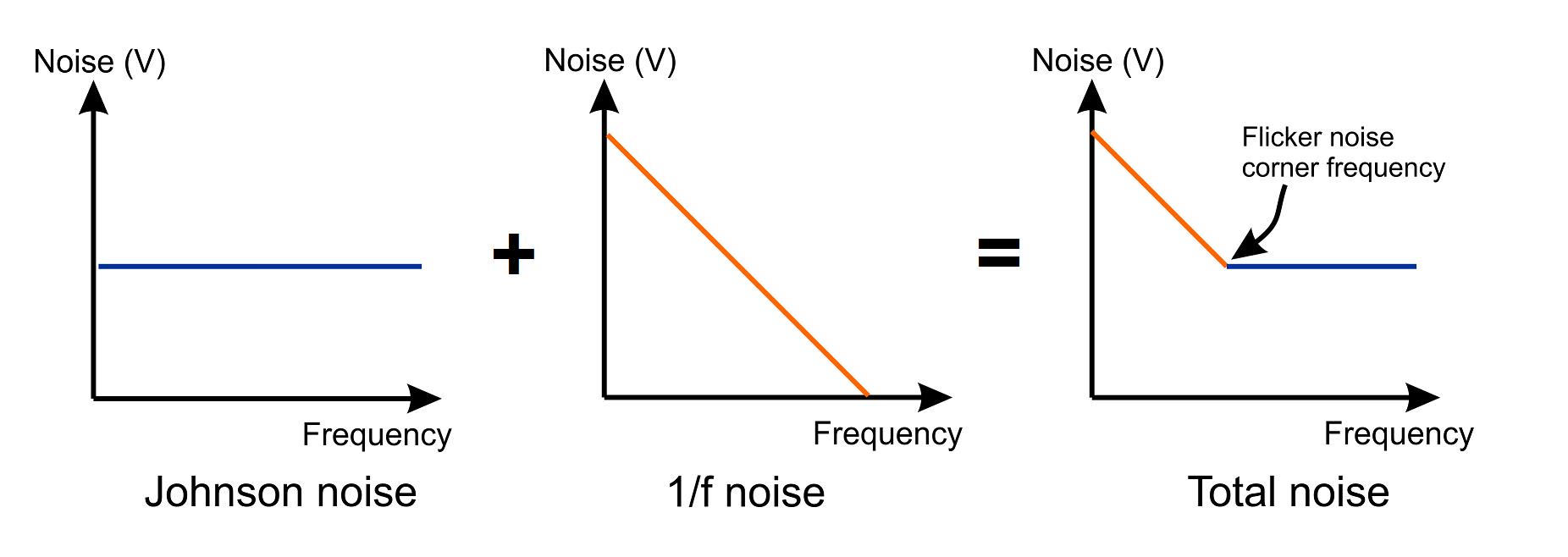 Flicker-noise is a type of noise which increases its magnitude with decreasing frequency, hence the alternative name of 1⁄f noise.
Flicker noise was observed first by J.B. Johnson of Bell Labs whilst he was attempting to confirm Schottky's theoretical prediction that noise in an amplifying vacuum tube would have a uniform (white) noise spectrum.
Johnson noted that, generally Schottky was correct but there appeared an unexpected increase in noise at low frequency. This was all the more puzzling because no classical theory could be found to explain this extra noise.10 Schottky suggested a mechanism for the extra noise and coined the term flicker effect.11
In the years following Johnson's discovery, it was found that this strange flicker-noise appeared again and again, and not only in different electrical devices, but in natural phenomena. For example it is present in measurements of ocean current velocity and sea level. Flicker-noise has been observed in biology, astronomy and economics.9 In fact, flicker noise has been recognised to be so ubquitous that its uncertain origin is today a major unsolved problem in physics.
According to classical physics, passing a current passing through a resistor should have no effect on its noise behavior; it should generate the same Johnson noise as a resistor with no steady current flow. However, a real resistor, with a constant voltage drop across it (and thereby a current flowing through it), generates flicker-noise in addition to its inherent Johnson noise. So, like shot noise, flicker-noise is associated with a DC current flow.
Flicker noise in passive resistors, is often referred to as excess noise, because it appears in addition to the thermal noise that is always there. The usual way of specifying the flicker noise due to a current in a resistor is in terms of µV/V' where V' is the voltage across the resistor.
Typical values for flicker noise in resistors are 0.1 - 3.0 µV/V for carbon composition types, about 0.05 - 0.3 µV/V for carbon film types and 0.02 - 0.2 µV/V for metal-film types. Wirewound resistors are normally completely free of excess or flicker noise.
In semiconductors, flicker noise arises from a number of somewhat arcane, physical mechanisms. It is thought that it derives partly from the generation and recombination of carriers on the surface of the semiconductor. It may be related to imperfections in crystalline structure as improved processing can reduce it.
As the graphs at the top of this section illustrate, 1⁄f noise may be modelled as an increase in noise below a certain frequency (ωf). To a degree, this is misleading because flicker-noise is generated at all frequencies — albeit with falling intensity. At some point, the flicker-noise falls below the level of the inevitable Johnson (thermal) noise and the frequency at which this happens is often called the flicker-noise corner-frequency. As the level of 1⁄f noise changes relative to Johnson noise, the value of ωf changes.
In a bipolar junction transistor, 1⁄f noise may be modelled as an increase in the current-noise generator below the flicker-noise corner-frequency (ωf); a parameter dependent on transistor type and sample.
The equation for In in a bipolar junction transistor was given in Appendix 1 as,
In = √ [4kTB ÷(2β/gm)]
where the terms are all described in Appendix 1.
We can modify this equation to account for flicker noise so that it becomes,
In = √ [4kTB ÷(2β/gm(1 + ωf/ω)]
The equation demonstrates that flicker noise is also dependent and proportional to collector current (because it's a function of gm), so that flicker noise is best avoided with the selection of low quiescent collector-current in a bipolar transistor.8 Because flicker noise appears on the current noise-generator it is not a great issue in transistor circuits when the source impedance is low.
In FETs and in vacuum tubes, flicker noise appears in the voltage noise generator.
The flicker noise in a FET is due to random fluctuations in conductivity of the drain-source channel and the generation and recombination of carriers on the surface of the semiconductor. The mathematical model for noise in a FET (see main text) may be modified so that it looks looks like this,
= √[ 4 k T B (0.67/gm) (1 + ωf/ω)] RMS volts
where ωf is the flicker noise corner frequency.
Flicker noise in tubes (valves) is generally thought to be caused by: irregularity and positive ions in the filament emission; remnants of gas in the envelope; and foreign deposits on grid wires due to imperfectly clean manufacturing spaces and techniques.
The equation for the noise generator in the tube is almost identical to that of the FET except that the term (0.67/gm) becomes (2.5/gm).
Given the litany of causes of flicker noise in a vacuum tube, it is no surprise that there is great variation between samples; even of the same nominal device. Sadly, whilst semiconductor manufacturers specify the flicker-noise corner-frequency (ωf) for their low-noise FET devices, equivalent data were never published for valves.
1. An Electrically "Cold" Resistance. Percival, W.S. THE WIRELESS ENGINEER May 1939
2. Improvement of the noise characteristics of amplifiers for magnetic transducers. Jean M. Hoeffelman and Rene P. Meys, Journal of the Audio Engineering Society, vol. 26, number 12, December 1978
3. A more formal explanation of noise due to the 47kΩ termination resistor
It's normal to think of the inevitable "natural" noise which is inevitably present in all resistors due to the thermal agitation of electrons as a voltage in series with the noiseless resistor.
The familiar equation for the RMS noise-voltage generated in any resistance by the random movement of the atoms (sometimes termed Johnson Noise) is called the Nyquist formula and has the value of:
= √[ 4 k T B R ] RMS volts
where k is Boltzmann’s constant (1.38 x 10⁻²³ joules/ degree Kelvin), where T is absolute temperature in degrees Kelvin (K = °C + 273), B is bandwidth in Hz, and R is the resistance.
If we substitute the values in the diagram, they give us a value of
≈ 4µV in a bandwidth of 20kHz at room temperature.
If we divide this figure by √B, it gives us a noise voltage "per root Hz" which is a useful quantity because that is how the input voltage noise of the preamplifier circuit is traditionally expressed.
In this case, the noise generated by the 47kΩ resistor is 28nV/√Hz which is about 10 times (20dB) higher that the voltage-noise in a first-class preamplifier.
At low frequencies where the reactance of cartridge inductance L is small, this noise source is in parallel with the low value of the winding resistance (500Ω) and is thereby swamped by Rw. But as the impedance of the cartridge inductance rises throughout the audio band, the noise performance of this circuit becomes more and more dominated by the noise-voltage Vnr due to Rt. The noise peaks at the resonant frequency of the cartridge inductance and the cable capacitance — and possibly the extra load capacitance in the preamplifier.
4. The noise mechanisms that these devices possess are: shot-noise on the anode-current in the case of a tube; and Johnson noise on the channel resistance in the case of the FET.
5. Measured as a comparison of unweighted noise in 20kHz bandwidth (results below).
| Configuration | EIN† voltage RMS unweighted in 20kHz bandwidth |
Relative noise in dB | S/N ratio relative to standard recording level* |
|---|---|---|---|
| Standard input (MM) | 4.9µV (-104dBu) | 0dB | 60dB |
| High gm FET buffer | 3.3µV (-107dBu) | -3.4dB | 63.4dB |
| FET buffer & Rt cooling | 0.68µV (-121dBu) | -17dB | 77dB |
† Equivalent Input Noise (output RMS noise voltage divided by preamplifier gain).
* Cartridge sensitivity taken as 5mV at 5cm/s velocity.
Note that these are unweighted noise figures prior to record equalisation (almost certainly RIAA for records where this degree of signal to noise ratio is relevant). As explained, the advantage of input cooling techniques is largely at the high-frequency end of the noise spectrum where the reactance of the inductive cartridge (or transformer) starts to become an appreciable part of the source impedance. RIAA equalisation and noise-weighting, which bias against high-frequencies, reduce the apparent effectiveness of the technique. This may have contributed to the lack of uptake in commercial RIAA preamplifiers; although - more likely - the innovation just arrived too late in the day.
In the case of a flat-preamplifier for needle-drop recording, there is no such bias against high-frequencies and input cooling genuinely increases recording resolution by nearly three digital bits - or even more at high (dual or quadruple) sample-rates.
6. Every bit in a digital PCM signal (or file) adds another 6.02dB dynamic range, so a 24bit PCM signal has 8 × 6.02 = 48dB more dynamic range than a 16 bit signal.
7. The Radiotron Designer's Handbook, F. Langford-Smith, Wireless Press, Sydney, Fourth edition, 1952
8. Noise in Transistor Circuits. Baxandall, P.J. Wireless World Nov, Dec 1968.
9. Flicker Noises in Astronomy and Elsewhere. Press, W.H. Comments in Astrophysics, 1978
10. The Schottky Effect in Low Frequency Circuits J. B. Johnson (Bell Telephone Laboratories, Incorporated, New York, N. Y.) Phys. Rev. 26, 71 – Published 1 July 1925
11. Small-Shot Effect and Flicker Effect. Schottky, W. Phys. Rev. 28, 74 – Published 1 July 1926

Address all mail to sales@phaedrus-audio.com
