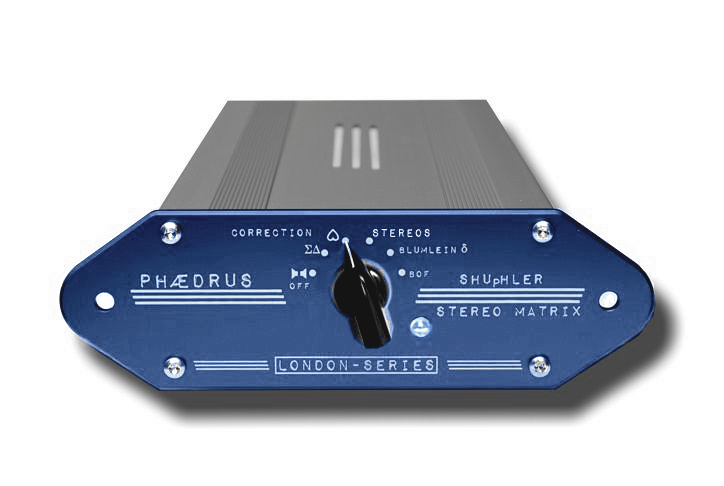
The Phædrus Audio SHUpHLER contains Blumlein's original shuffler circuit, (which permits pin-point sharp stereo recordings to be made with near-spaced omni' microphones) and the Stereosonic shuffler developed for the famous tube consoles of the 1960s.
 In addition, the unit provides the well known FRANCINSTIEN stereo enhancement, and an entirely new stereo correction technique for crossed cardiods, ORTF and NOS arrays.
The new SHUpHLER III supports full balanced/unbalanced operation with maximum levels to +18dBu. Signals may be balanced in/out or a mixture of the two. All circuitry is class-A for very low noise and distortion.
The SHUpHLER III has a completely re-engineered matrix to improve upon the previous SHUpHLERs and is available in the London Series blue livery. We are accepting orders for this unit NOW!
Read the Sound on Sound magazine review of the Phædrus Audio SHUpHLER.


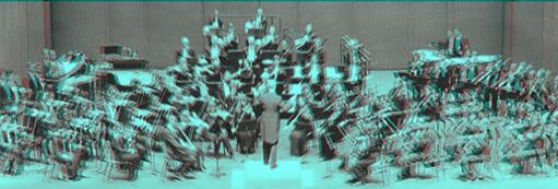
Just a quick note to say how impressed I have been with the Shuphler. I have it hard-wired into the final stage of my mixing/mastering chain, and it has been used in studio and live-mixing situations. I engineer Classical Music predominantly, and the ability to "glue" the stability of the stereo image using the various Shuphler settings (depending on the mic'ing) has made a huge improvement to the results of my labours. I use a lot of spaced pairs simultaneously, and to run them all through the Shuphler (usually Blumlein setting) makes for a much more forceful "presence" of the Orchestra and Soloists. It is an essential piece of my audio chain now.
Cheers, Michael Conolan

It's so important to remember that a stereo recording is a matrixing of spatial information into a correlated pair of signals: like the way 2 colour-difference signals describe all the colours in television. Stereo really isn't "dual mono" and there exist ways of releasing information apparently "trapped" in the signal. Richard Brice
Here's some of the way I've found to use my SHUpHLER III: Creating headphones mixes from a stereo master (I've even used it to mix on headphones with good results); creating 3D audio stems from binaural recordings (for TV work); improving stereo image of all types of stereo recordings; enhancing dry and/or "boxy" stereo mixes and stems; creating more energetic mixes by throwing more energy into the sub'; the list goes on......
Beta tester of SHUpHLER III

Despite being discussed since the earliest days of stereophony, there remains much confusion about the term Stereo Shuffling. This is not surprising because the term actually refers to two, quite separate and different techniques.
Simply put, the earliest use of the term (coined by no less than Alan Blumlein himself), refers to the processing of near-spaced omni' microphone signals so that they reproduce correctly on loudspeakers.
The second Shuffler was invented some twenty years later for the processing of crossed, cosine (figure of eight) microphone signals to give better realism.
Why use the same name? Well the later "Shuffler" was invented by the same team who had worked with Alan Blumlein before he was killed in the Second World War. Perhaps they sought to honour him in adopting the term which derived from him?
In any case, the Phædrus Audio SHUpHLER III incorporates both type of historical Shuffler, plus some newer shuffling (or matrix) processes, so that you can experiment and use these amazing techniques on your own recordings.
The Phædrus Audio SHUpHLER III is a line-level device which employs entirely class-A circuitry for the matrix buffering and line driving. Inputs and outputs are fully balance/unbalance compatible. The device has a high overload margin (>+18dBu at 1kHz), and low-noise, so that it's equally useable connected at insert-points, across the stereo bus/ stereo signal or used in a balanced or un-balanced send-return loop with a DAW.
The front panel of the SHUpHLER III is simplicity itself. In addition to the "off" position, five selectable shuffling techniques are available, each of which is described below.
 This is effectively the "OFF" position. In this position, the input signals are left unprocessed and simply pass through the unit.
ΣΔ - Neumann elliptical equaliser
Vertical modulation of the cutting stylus must be limited when cutting records because, if these modulations aren't carefully restricted, at the peaks of the wave the cutter chisel either digs so deep that it scrapes the aluminium substrate of the lacquer master disc or it produces a groove so shallow that the stylus slides out on playback.
Out-of-phase information, or excessive L-R information is especially problematic when cutting a record because it causes these vertical movements of the cutter.
Read about cutting records here
Mindful of the above, recording engineers are all taught not to plague their recordings with excessive energy in the channel-difference signal (bass and bass-drum are usually panned to the centre and so on). But large amounts of low frequency channel-difference energy can arise due to operational oversights. For example, spaced microphones can respond to very low-frequency air-conditioning or traffic noise and, by dint of their physical spacing, result in excessive channel difference information. The recording engineer, listening on small loudspeakers, may be completely unaware of the effect until the horror is unleased on the disc mastering team.
To contend with problems such as these, lathe electronics include a piece of equipment dedicated to eliminating vertical modulation below a certain frequency known as the elliptical equaliser.
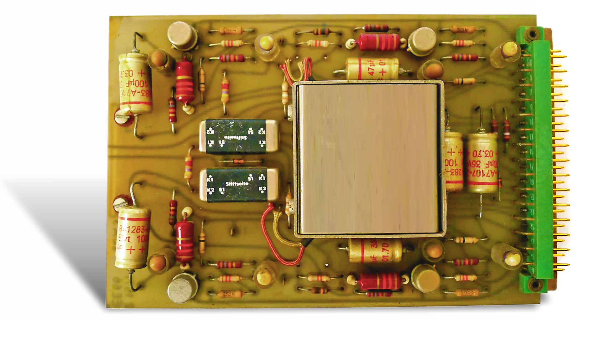
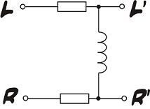 This special equaliser (in the case of Neumann’ lathes, the EE66 or EE70) is a relatively simple
device, at the heart of which are just three impedances. The reactance of the cross-feed inductor (visible within its mu-metal can in the image of the EE70 above) is substantial at high-frequencies which ensures good channel separation. But, as the reactance of the inductor falls with reducing frequency, the channels separation is reduced until – at a theoretical zero-frequency, when the reactance of the inductor is zero – the resulting L’ and R’ signals are
identical and no channel-difference information exits at all.
This special equaliser (in the case of Neumann’ lathes, the EE66 or EE70) is a relatively simple
device, at the heart of which are just three impedances. The reactance of the cross-feed inductor (visible within its mu-metal can in the image of the EE70 above) is substantial at high-frequencies which ensures good channel separation. But, as the reactance of the inductor falls with reducing frequency, the channels separation is reduced until – at a theoretical zero-frequency, when the reactance of the inductor is zero – the resulting L’ and R’ signals are
identical and no channel-difference information exits at all.
The elliptical equaliser in the Phædrus Audio SHUpHLER may be used in several ways. Clearly, it may be used as Neumann intended; to reduce problematical signals for a project destined for vinyl release. But, it may also be used to concentrate bass and bass-drum signals within the mix, and it works very well as a headphone shuffler - making mixes easier to judge on headphones. Or make listening simply more enjoyable on headphones.
Recordings with instruments panned full left or full right produce a particularly odd sensation when reproduced with headphones. Early Beatles recordings are famous for this early stereo technique, as are many Blue Note jazz recordings. These recordings offer a very striking demonstration of the great advantage of elliptical shuffling technique for headphone listening and one, short example is offered here. The first 25 seconds is the standard stereo signal: the shuffled version follows.
Even more striking is this example of hard panned narration. Once again, the first part is standard stereo: the second part is elliptically shuffled. Note how the first part sounds really freakish and how the second part sounds more natural and normal. Also note that the equal-energy design of this shuffler ensures that there is no change to the timbre and tone of the voice when the shuffling is operative.


The directional response of a cardioid microphone is equivalent to the combination of a cosine (figure-of-eight) and omni-directional response. (In fact, the earliest cardioid microphones were made in this way). So, the signals from a crossed-pair of cardioid microphones are mathematically equivalent to those produced by a crossed pair of eights, mixed equally with a mono signal. It's not surprising this technique is often accused of lacking "spaciousness". The truth is, the only reason the crossed-cardioid technique gives reasonable results is due to the HF "beaming" of the microphones which cause high-frequency channel differences to predominate over the mono signal at higher frequencies.
 One way to improve the situation is to set the microphones at a greater angle than 90 degrees, or separate them slightly, so as to add a time-delay "helper" cue, as is done in the ORTF and NOS arrangements. But, it is also possible to correct for the effect of the unwanted, omni-response electrically; and that is what is done in the SHUpHLER when the switch is in the ♥ position.
One special advantage of the electronic process is that the correction results in a suppressed rear-lobe. Because this looks like half of an eight response (see diagram), we term this technique, Phćdrus crossed-fours™. Musical examples of the crossed-fours technique are given below.
The first part of each musical extract (taken from rehersal tapes) is the signal direct from the microphones and the reprise is treated with the "crossed four" process.
FRANCINSTIEN - Stereosonic shuffler
When the British team developed the Stereosonic, two-channel, stereo recording system after the war which killed its inventor Alan Blumlein, they incorporated special circuitry which corrects for known problems with a standard stereo signal.
In naming this special circuit, its inventors (H. A. M. CLARK, G. F. DUTTON and P. B. VANDERLYN) honoured their old boss (Blumlein) in borrowing the term he had coined for an earlier stereo processor and called it the Shuffler. Unfortunately, this borrowing of the earlier term has led to much confusion about stereo "shuffling" over the years because a "stereo Shuffler" is actually two, quite different inventions which share a common name!
For a full description of their work, Clark (et al.)'s paper is available here.
In effect what Clark, Dutton and Vanderlyn found was that, a standard, panned stereo signal (or that derived from crossed-mic's) has the drawback that, for a given position away from centre, or of the pan-pot away from the centre, the high-frequency components of a signal actually appear further from the centre in the reproduced "stereo-image" than do the lower frequency components. This is directly reproduced from their 1958 JAES paper.
The circuit to introduce the 0.7 loss-factor in the ratio (R - L)/(R + L) above 700Hz is the circuit Clark and his team called the Shuffler. To avoid confusion, we suggest that Clark's circuit be termed the Stereosonic Shuffler, reserving Shuffler for Blumlein's original circuit (more on this later!).
The result of not utilising this Stereosonic Shuffler, on a real music signal is a "smeared" stereo image in which the high and low frequencies are not "mapped" on top of one another. The image below is an attempt to give a visual analogy for this effect in which the acoustic effect is analogous to chromatic aberration in a lens, in which the high frequency blue light is refracted differently to the low-frequency red light.
The solution to this was to incorporate sum and difference circuits into the stereo bus of the mixers (derived in a series of transformers) and introduce HF loss into the difference circuits so that, when matrixed back to left and right signals, the required correction had been made.
This method however has the disadvantage that the HF-loss filter-circuits require phase-correction to be applied and moreover require that the sum circuit be delayed.
The result, together with the matrixing transformers, is a very expensive assembly, illustrated below.
This expense, as well as irresolvable problems of slight audio colouration due to inaccuracies in the phase-correction circuits (note the hand-written "almost" and "substantially" in the text above.), led this vital circuit to be ignored in later stereo equipment. Uncorrected stereo was reckoned to be "good enough".
It's important to point out what this actually means: that all stereo recordings are "broken" and have been since Electronic and Musical Industries' management sanctioned throwing the last of their tube mixers on the dumpster. (Yes, they really did that!).

The SHUpHLER incorporates the implementation of the Stereosonic Shuffler known as FRANCINSTIEN which was developed by Perfect Pitch Music back in the 1990s in which the uneven frequency-response and group-delay problems of the original implementation were entirely resolved.
An example of the FRANCINSTIEN Shuffler process is given here.
The first part of the musical extract is the signal direct from crossed-cardioid microphones and the reprise is treated with the FRANCINSTIEN process.
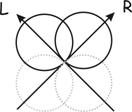
The greater part of Alan Blumlein's (1933) patent is concerned with a binaural stereophonic microphone arrangement in which,
"two pressure microphones a1 and a2 [are] mounted [20 cm apart] on opposite sides of a block of wood or baffle which serves to provide the high frequency intensity differences at the microphones in the same way as the human head operates upon the ears".
Blumlein noted that, when listened to with headphones, the direct output from the microphones produced an excellent stereo effect but, when replayed through loudspeakers, the stereo effect was very disappointing. The transformation Blumlein required was the translation of low-frequency, inter-microphone phase differences into inter-channel intensity differences. To do this, he invented an ingenious circuit which he called the Shuffler. (His was the original use of the term.) A modern implementation of Blumlein's circuit is implemented within the SHUpHLER. The full technique is explained here.
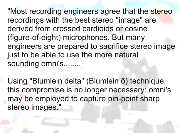
The advantages to the recording engineer of this technique are legion. Omnis are usually considered to sound slightly more "open" and "uncoloured" than their cardioid brothers; even as mono microphones. This is due to the acoustical devices which cardioid mic's employ to deaden the sound in the rear lobe of the directional response. Most agree that the stereo recordings with the best stereo "image" are derived from crossed cardioids or cosine (figure-of-eight) microphones. But many engineers are prepared to sacrifice stereo image just to be able to use the more natural sounding omni's.
Using "Blumlein delta" (Blumlein δ) technique, this compromise is no longer necessary: omni's may be employed to capture pin-point sharp stereo images. The microphones should be placed about 22cm apart (not widely spaced as in conventional technique). Various baffles may be inserted between the microphones to good effect too, so this technique suits various binaural and quasi-binaural microphone arrangements like the Jecklin's OSS disc, Faulkner's "Phased-array", the various spherical microphone baffles and the in-ear microphones available on the market. (In fact Blumlein saw the δ technique as a binaural to loudspeaker-stereo conversion process: which is what it is!)
An example of the process is given here as a FLAC file. Once again, The first part of the musical extract is the signal direct from near-spaced omni microphones and the reprise is treated with the Blumlein δ process.
The technique of near spaced microphones may even be extended to use near-spaced cardioids which enables very nice recordings to be made which suppress rear pick-up. In fact, even hyper-cardioids and gun microphones may be employed which permit good, full-width stereo recordings to be made of relatively distant events - something which no other technique can achieve. This has obvious applications of 3D Audio to TV, film and live theatre and music. For example....
The first demo is of American folk singer Suzy Bogguss and is a recording of a rehersal in her home with the various musicians disposed around the binaural array. The first part of the recording is the original binaural version (listen to this on headphones). The second part (01:05) is processed in SHUpHLER to generate a binaural effect from stereo loudspeakers.
The second example is of binaural street recording in New York. Once again, the first part of the recording is the binaural version (listen to this on headphones). The second part (01:00) is processed in Stereo Lab to generate a binaural effect from stereo loudspeakers.
stands for Bride of FRANCINSTIEN which is very new shuffling technique. The BoF technique is a development of the original FRANCINSTIEN circuit which was launched during the 1990s.
Phædrus Audio recommend that you experiment with both the BoF matrix and the original Stereosonic matrix for processing panned-stereo recordings and for processing stereo signals derived from crossed microphones. We conjecture that, because all, practical microphones tend to "beam" and become more directional with frequency, recordings made in this way have an even greater frequency-dependant smearing effect compared with those derived entirely from pan-pots. Because the Stereosonic matrix position introduces a greater degree of HF narrowing than does the newer BoF matrix, it may better compensate for HF beaming effects in crossed microphone recordings. However, as with all things in the art/science of recording, it's unwise to be pedantic: experimentation is the name of the game!
An example of the BoF Shuffler process is given below.
The first part of this musical extract is the signal direct from the mixer and the reprise is treated with the Bride of FRANCINSTIEN shuffler process.
| Mic' arrangement | Elliptical | ♥ | FRANCI | Blumlein δ | BoF | OFF |
|---|---|---|---|---|---|---|
| Crossed cardioids | Good results | Ideal*: Crossed-fours™ | Good results | Not suitable | Good results | No processing |
| Crossed cosines | Good results | Possible; widens image | Ideal* | Not suitable | Good results | No processing |
| Pan-pot | Good results | Possible; widens image | Good results | Not suitable | Ideal* | No processing |
| Near spaced omnis | Good results | Possible; narrow image | Worth a try! | Ideal* | Worth a try! | No processing |
| Near spaced cardioids | Good results | Possible; narrow image | Worth a try! | Ideal* | Worth a try! | No processing |
| Near spaced hypercardioids | Good results | Possible; narrow image | Worth a try! | Ideal* | Worth a try! | No processing |
| Binaural microphones | Good results | Possible; narrow image | Worth a try! | Ideal* | Worth a try! | No processing |
| Phased array cosines (Faulkner) | Good results | Possible; narrow image | Good results | Ideal* | Good results | No processing |
| Wide spaced omnis | Good results | Not suitable | Good results | Not suitable | Good results | No processing |
| NOS | Good results | Worth a try! | Good results | Good results possible | Good results | No processing |
| ORTF | Good results | Worth a try! | Good results | Good results possible | Good results | No processing |
| Decca Tree | Good results | Not suitable | Good results | Not suitable | Good results | No processing |
Size: 112 × 50 × 225 mm (W-H-L)
Power Supply: Low-noise +12V DC input on screw locking connector
Power: Compatible with European Eco-Consumption directives*
Inputs: Balanced or unbalanced on 3-pole 0.25” jack. Tip is "hot".
(Unbalanced: tip = signal, ring and body = earth)
Gain: 0dB non-inverting, in balanced or unbalanced operation
Frequency response: 5Hz to 1MHz (-1dB) in bypass mode
Distortion: Better than 0.005% THD on 1kHz at 0dBu input
Equivalent input noise: -112dBu (bypass mode, A weighted)
Max input: Greater than 18dBu balanced†: +12dBu unbalanced
Max output: Greater than 18dBu balanced†: +12dBu unbalanced
Headroom indicator: Operation LED (normally blue) flashes red at level -1dB from headroom limit
* The unit is intended to remain energised all the time and still conforms with the European Union's Ecodesign Directive (Directive 2009/125/EC).
† Operation according to EBU R64-1992: PPM4 = 0dBu = -18dBFS
Phćdrus Audio reserves the right to alter specifications without notice.
 "Listening to Blumlein-shuffled, near-coincident recordings adds tremendous LF "bloom" and LF directivity.... teasing information out of the stereo signal I recorded twenty years ago that I never knew was there. Extraordinary - like an archaeologist putting a Egyptian Mummy in an MRI scanner!
It's so important to remember that a stereo recording is a matrixing of spatial information into a correlated pair of signals: like the way 2 colour-difference signals describe all the colours in television. Stereo really isn't "dual mono" and there exist ways of releasing information apparently "trapped" in the signal."
Richard Brice
Address all mail to sales@phaedrus-audio.com