The Phædrus Audio alignment protractor is a universal tool which allows the choice of Löfgren (Baerwald) alignment or Stevenson alignment. It also offers a universal scale for checking tracking error over the entire disc surface and for checking tracking error for 7-inch records.
It further includes a unique, and simple means of calculating the dimensions for correct alignment.
All modern tonearms are arranged so that the stylus swings beyond the distance between the turntable spindle and the tonearm pivot point This is called the overhang of the tonearm. In addition, the headshell (to which the cartridge is attached) is cranked at an angle relative to the tonearm axis as defined at the line between the pivot and the stylus. This is known as the offset angle of the tonearm.
By these two means, tracking error is arranged to swing either side of zero as the tonearm moves across the surface of a record with the tracking error being zero at two, precise radiï. By defining the points at which the tracking error is zero (referred to as null-points), a condition of minimum average distortion may be obtained across the entire playing surface. That is the role of the alignment protractor.

The .pdf book comes with a a high resolution, printable .pdf file copy of the alignment gauge.
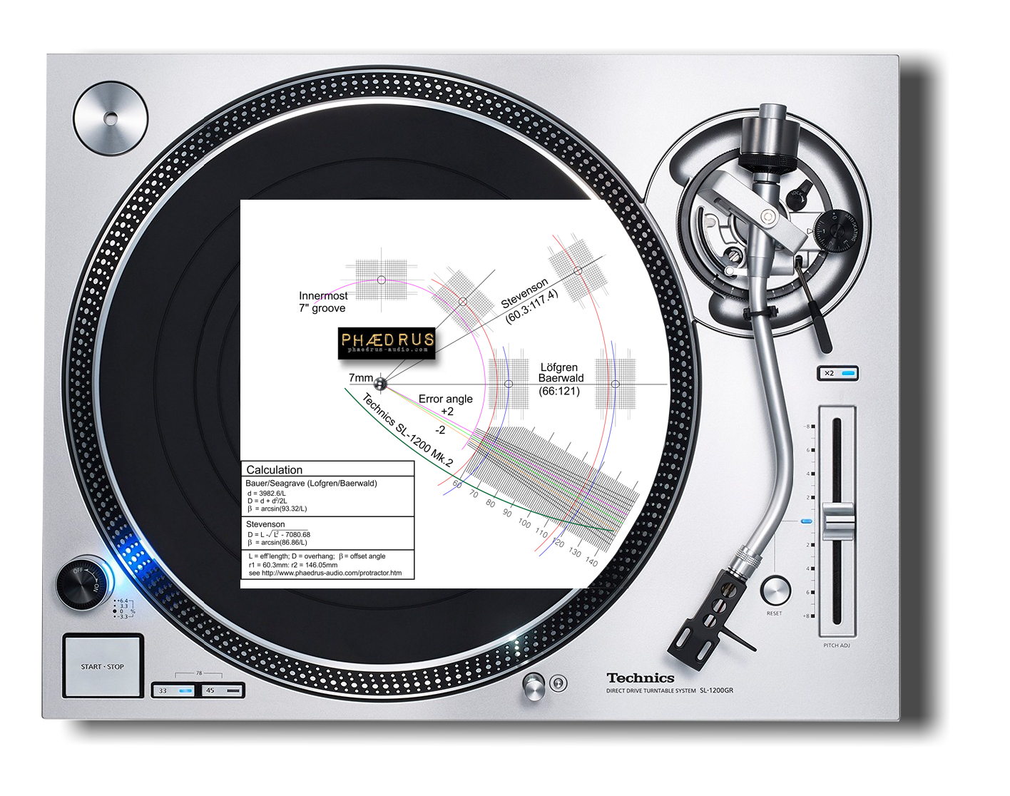
Once printed and the dimensions checked with a ruler to ensure that no scaling has taken place in the printing process, the Phædrus Audio alignment gauge should be trimmed (as indicated) and fitted over the turntable spindle. A hole of 7mm must be punched or carefully made with multiple pricks of a pin around the circumference.
The null points - where tracking angle errors should be zero - coincide with the radiï where the longintudinal axis of the cartridge lines up exactly with the tangential grid lines of the protractor as shown below.
Null points are indicated for the most common (Löfgren/Baerwald) alignment at the 3 o'clock position on the alignment gauge. This solution was derived by Löfgren in 1938 and derives a solution for minimal average distortion over the playing surface of the record¹. The solution was disseminated in the English speaking world by Baerwald a few years later, in 1941².
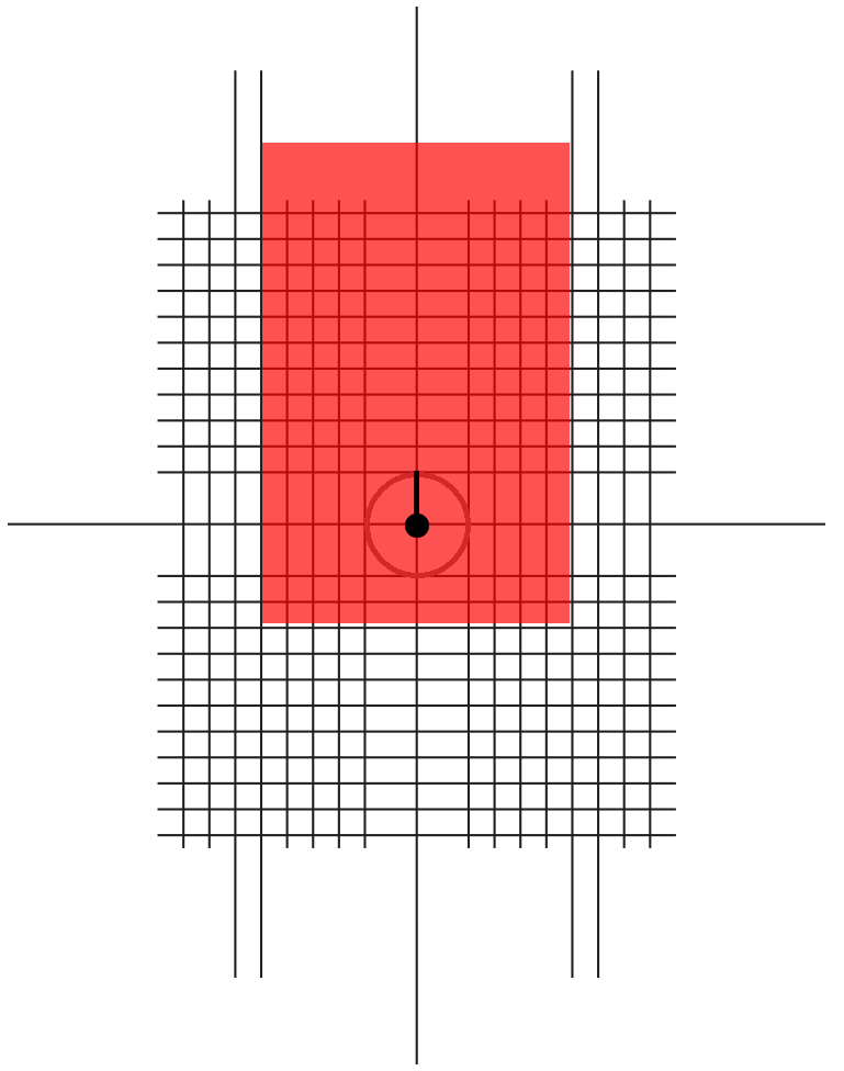
The cartridge should be fixed in the tonearm headshell, but with the fixing bolts loosened. It is most convenient to place the cartridge so that its fixing bolts are in the middle of the travel permitted by the slots in the headshell. Position the stylus so that it sits at the target of the inner Löfgren/Baerwald grid-box. By twisting the cartridge, it should be aligned so that the sides (and front) of the cartridge best align with the lines of the grid-box. Here you are adjusting the offset angle of the stylus (β) relative to the tonearm axis.
The tonearm should then be positioned so that the stylus sits in the target of the outer grid-box. By shuffling the cartridge forward or backwards (trying not to change its angle) alignment should be adjusted to give the best parallelism with the tangential lines in the outer box. Here you are adjusting the effective length of the tonearm (L) or its "overhang" (D).
By iterative adjustment, alternating between the inner and outer grid-boxes, and using gradually smaller and smaller refinements of angle and overhang, it should be possible to accomplish good parallelism between the cartridge body and the grid-box lines at both positions. (If it isn't, it may be that the tonearm has been incorrectly installed.) Once the best alignment has been found, the cartridge fixing bolts should be tightened carefully; taking care not to move the cartridge relative to the headshell in the process.
The alignment gauge will need to be rotated back and forth as the iterative adjustments are made. DO NOT rotate the turntable with the stylus resting on the protractor (especially anticlockwise). Our advice is to keep the preamp' volume up a little way. This will reveal - and discourage - any tendency to scrape the stylus against the protractor.
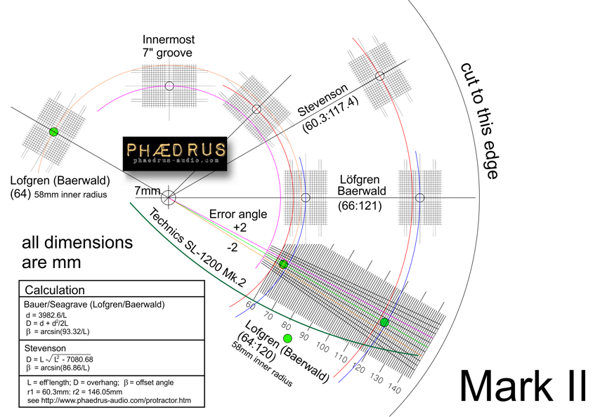
The only real alternative to Löfgren/Baerwald is the alignment of Stevenson³. The two null points for this alignment are also available on the protractor (at the one and two o'clock positions). The same iterative procedure is used to accomplish this more modern alignment.
Stevenson took a different approach to Löfgren (or Baerwald), who had argued for an alignment which caused the minimum average distortion over the whole playing surface. Stevenson pointed out that all other distortion mechanisms worsen as the stylus approaches the innermost groove. Since in lateral tracking distortion we have a mechanism which may be minimised at the innermost radius, that is the approach we could take.
It's a good argument. Many of the other distortion mechanisms in cutting and reproducing records weren't understood in Löfgren's day. And remember that, to Löfgren and Baerwald, the word record meant a lateral-cut, shellac-slate "78" with no deëmphasis: whereas, to Stevenson, a record was a PVC copolymer, RIAA equalised, stereo LP. Löfgren was writing a sparse ten years after the invention of electric recording, nearly 30 years would pass before Stevenson's analysis.
Address all mail to sales@phaedrus-audio.com

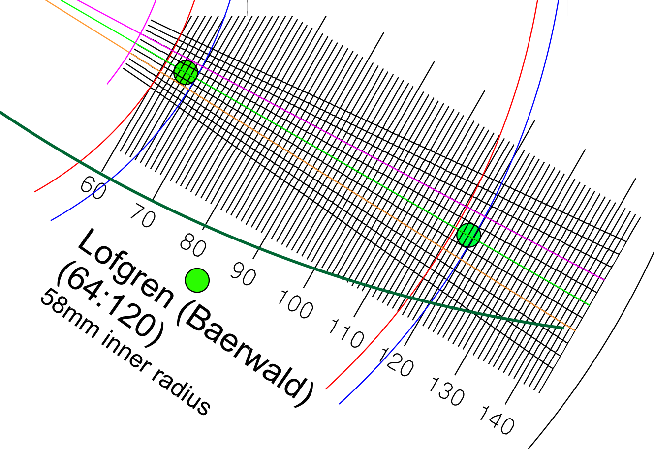 Other standards organisations seem to have had different ideas. British Standard (BS1928-1965) fails to specify any inner radius limit. German standard (DIN45547-1981) and the Japanese industrial standard (JIS S8502-1973) specified a minimum recorded radius closer to 58mm. These differences of opinion led to an international standard (IEC98-1987 or IEC 60098) based on the harmonisation of national standards in which no inner radius limit was specified at all!