As fans of The Beatles, Phædrus Audio have researched and been influenced by Beatles recording gear. The definitive work is, Recording The Beatles). However, although a beautiful and absorbing book, it is not especially technical. So below is some of what we have researched and discovered about "FAB gear" for the "techies" out there!
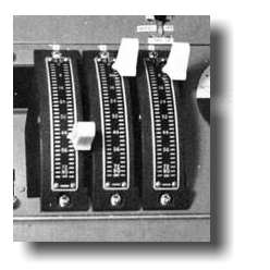
The Stereosonic Consoles
Built in the late fifties at a cost of about £125,000 each, and weighing-in at about 350kg, the British Stereosonic consoles were based on the work of Peter Burkowitz in Cologne who invented the famous, logical and symmetric control surface.
Engineer Len Page set up a new division at Electrical and Musical Industries called the Record Engineering Development Department and worked with Burkowitz to develop consoles for the British studios.
Read more...
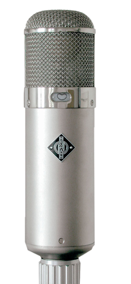 The U47 microphone was developed by the German company Neumann and was launched in 1947. It is common to see Neumann, Telefunken and Siemens "versions" of the U47 because Neumann OEM'ed the microphone to Telefunken and Siemens who stuck on their own badges, but all U47s were manufactured by Neumann.
The U47 is deservedly a legendary microphone. Ella Fitzgerald and Billie Holiday both recorded using the U47. Sinatra refused to record without his "Tele" (Telefunken U47), and the microphone was the first choice for the early Beatles records; both for vocals and guitar. George Martin called the U47 his "favourite microphone".
The impedance-converter of the U47 uses the now, very scarce VF14M tube which acts as a voltage amplifier circuit and drives the output transformer which translates the output impedance to 50 or 200 ohms to drive the long microphone cable.
Unfortunately, the VF14 (which in any case had to be selected) is now so rare that it is almost impossible to get a tube which performs so that the microphone approaches its specification.
It is because of this that Phædrus Audio developed the new VF14M electronic tube.
Stereosonics
The Stereosonic consoles are mostly famous for their use on The Beatles records. However, these mixers were not conceived for stereo pop music sessions.
From the start they were designed as stereo mixers for classical music recording. In fact, the mixers were designed as Stereosonic mixers - devices which would permit two channel recordings according to the theory invented by Blumlein and later developed by Clark, Dutton and Vanderlyn (Ref is here.).
Various design assumptions underlie the architecture of the "Stereosonic" mixers. Principal among them, that the recording signals would derive from a stereo microphone pair plus possible other panned "spot" microphones and that the resulting signals would be simultaneously recorded on four separate tape tracks as two stereo pairs.
This assumption is "hard-wired" into channels and the busses on these mixers. For this reason, the mixers do not permit stereo panning on the tape returns as we expect to see on a modern console. Instead, simple switches on the tape-input channels are provided to allocate individual tape tracks to stereo-left and stereo-right during mixdown.
Though evidently ideal for the recording of classical music, this forced some compromises on producers and balance engineers working on stereo, pop sessions in which mono tracks were combined in a final stereo image. These compromises were especially evident during mixdown.
Whereas the non-panning nature of these input channels made good sense when the goal of the mix was to "reduce" two stereo "pictures" to a alloyed stereo master, it didn't suit the mixing of essentially mono instrumental and vocal tracks into a stereo image. This limitation accounts for the very quaint early, stereo Beatles records in which the rhythm track appears entirely to come from one channel and overdubbed or solo instruments on the other.
For some of The Beatles' tracks, by clever misuse of certain of the consoles features, the vocals were forced into the centre of the stereo field. But this was not always the case, and many of The Beatles stereo mixes feature the vocals hard-panned left or right: a fact that has become a blessing to maverick, DJ, remixers in recent years! Only with the introduction of eight-track recorders, and the subsequent neccessity to feed all tape channels back into the console, were mixer channels 3, 4, 5 and 6 and their pan controls available during mixdown: an accidental phenomenon, but one which permitted conventional panning practice to evolve.
In fairness to the designers of the Stereosonic consoles, the limitations to the panning of tape-returns was no oversight. Stereo pop music mixes were not considered important during the late fifties and early sixties when these consoles were designed. Naturally, the lack of panning is of no consequence during a mono mix.
Here is a simplified system diagram of the famous Beatles' Stereosonic console.
Stereosonic console signal flow
The Stereosonic (.37) "4-Track Mixer" is very similar to the later (.51) 8-track console, the only difference being cosmetic and that the .37 used German modular line-amplifiers, rather than the British made Record Engineering Development Department .47 amplifiers. In terms of overall signal levels and impedances, the operating level of 0dBm into 200 ohms is universally adopted.
A third position on the input switch (just on channels 1, 2, 7 and 8) allows the tape-return tracks to be applied to these circuits during mixdown. Input selection is followed by a constant-impedance attenuator and thence to a three-way selector which provides the choice between: 10dB bass-lift (for distant, velocity microphones which tend to be bass-light); a 10dB attenuator (for close microphones); or a straight-through path. The signal then passes to the first of the amplifier modules and thence to the equalisation circuits, which are no more than boost/cut tone controls for treble and bass. Alternative equalisation responses were made available for engineers working on classical sessions and their pop-session colleagues by means of having the reactive components within the EQ circuits available in plug-in modules which fitted below the control surface. The Classic version of the equalisation provides shelving responses via entirely passive circuitry with a range of +/- 10dB in 2dB steps. The "Pop" circuits are a little different. As the design engineers put it in documentation still surviving put it,
.....[the "Pop" circuits are] 'fiercer'. The bass control operates not only on the extreme bass but also has considerable effect on the higher bass frequencies. Similarly the top control operates at a much lower frequency than normal. The top cut is of the usual 'stepped' type but the top boost consists of a circuit which is broadly tuned to 4,700 c/s [Hz].
The insertion loss of the EQ (all control flat) is 10dB and the signal then passes to the main channel fader; a Painton manufactured, quadrant, constant-impedance device.
Channels, 3, 4, 5 and 6 are nearly identical; except for the tape inputs. But - whereas channels 1, 2, 3 and 4 feature bus selection after the fader, the remaining inputs provide for splitter transformers to drive the pan pots; these devices being complementary, bridged-T, constant-impedance networks with 3dB overall loss. The pan pots are not continuous and provide for 5 equally spaced angular positions either side of centre. In the same circuit position, channels 1, 2 and 7 and 8 incorporate the stereo Spreader control which is described later. The signal then passes to the combiner circuit, an intermediate amplifier (known as the "Inter Amp" and derived from the German term "Swischen-Verstarker" or "between-amplifier") and thence to the main fader and line amplifier.
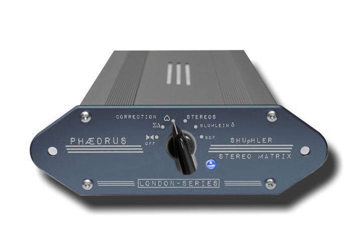
The Shuffler is an essential component of a practical stereo system and one that got forgotten for many years following the "retirement" of the Stereosonic consoles. The Phædrus Audio SHUpHLER reintroduces the Shuffler features so that you can rediscover "Stereosonics" in your own studio.
Type 47 modular amplifiers
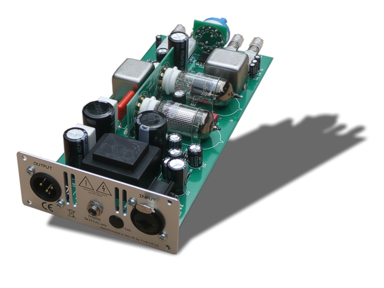 The Type 47 modular amplifier was developed and built as a line amplifier to be used between control networks (faders, EQ, pan-pots) for studio's own sound mixing consoles. Len Page's group (Record Engineering Development Department) developed this amplifier in reaction to the very high price they were obliged to pay for the German modules used in their earlier consoles as the Deutschmark surged against the pound in Germany's booming, post-war economy.
The Record Engineering Development Department Type 47 modular amplifier offers three, selectable gains of 34dB, 40dB and 46dB. The amplifier is housed in its own modulular frame. Unlike the V72, the British variant did not contain its own mains power supply. Instead it was fed from a 380V to 400V DC supply within the mixer chassis and sub-regulated to 300V within the module. Heater supplies were AC. The module is therefore more difficult to support as a stand-alone unit.
The Type 47 modular amplifiers have a custom transformer. The output stage is more innovative and is based on the dual-triode ECC88 (E88CC in the original design). The two halves of this second valve stage are "strapped" (connected in parallel), to raise the transconductance of this stage and lower the anode-impedance. This is desirable because it aids the voltage drive to the output transformer. This latter component has a winding ratio 7:1 + 1 and an impedance transformation of 10K to 200 + 200 ohms. The bandwidth of the transfomer is 10 Hz to 50 kHz when fed from an equivalent circuit. Once again, these transformers were specially built.
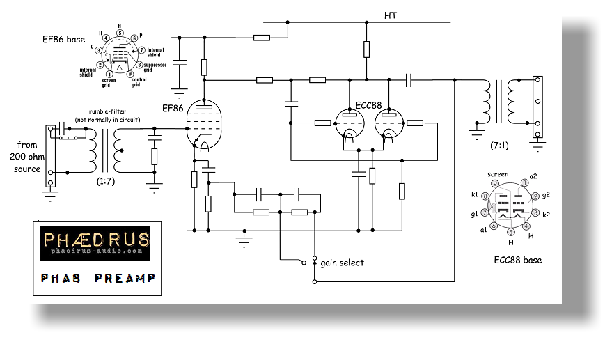 The mutual conductance of the ECC88 triodes is high (25mA/V with two valves in parallel). The maximum, open-loop gain of the output-stage to the anode of V2 is the transconductance times the anode resistance of the triodes in parallel: about 33 times or 30dB. However, this figure is modified by local feedback - provided by the high value resistor and capacitor from the anodes of the second valve, to the coupled grids.
By arranging local feedback around this harder working stage, a value of second harmonic distortion was obtained which matched that of the input stage for a given drive voltage. By virtue of the fact that the second stage is inverting, the second-harmonic distortion generated in the second-stage is out-of-phase with that generated in the first: the result being that the second harmonic cancels out; in practice down to the level of the third-harmonic.
Naturally, the gains of the two amplifier stages adds together and this produces a figure of approximately 57dB (700 times) for open-loop gain. This figure is reduced by loop, negative feedback from the anodes of the E88CC triodes to the cathode of the EF86 which is left unbyapssed. By arranging a switched network, closed-loop gain may be controlled over a small range by adjusting the feedback fraction via a front-panel switch as illustrated below.
A plastic-cap covered "tweak" pot is accessible from the front of the amplifier to adjust the gain values as the open-loop gain changes due to valve ageing. The HT of the preamp is carefully regulated via series neon regulator tubes and much has been written about this as a contribution to the sound.

Address all mail to sales@phaedrus-audio.com