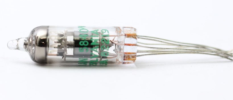
 The AC701 triode valve was the result of collaboration between Telefunken and Nordwestdeutscher Rundfunk (Northwest German Broadcasting) specifically to develop a miniature active device for capacitor microphones. It was designed with that specific audio application (and only that application) in mind. That meant designing for low-noise and low grid-current. The CK5840, on the other hand, is a special quality version of the EF732 pentode, developed as a UHF amplifier. The maker's described the 5840 tube as, "for use in high frequency circuits under conditions of severe shock, vibration, high temperature and high altitude." In other words, they could hardly be more different valves. You might say that the AC701 has its origins in warm microphones, and the 5840 has its roots firmly in the Cold War!
In other words, they could hardly be more different valves. You might say that the AC701 has its origins in warm microphones, and the 5840 has its roots firmly in the Cold War!
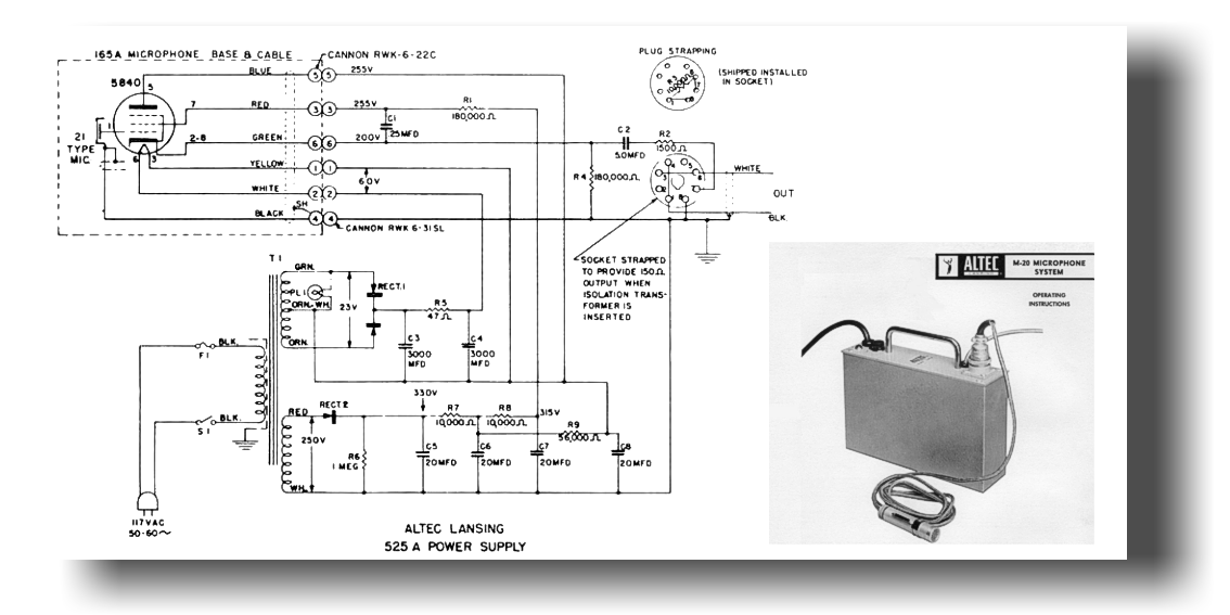
The 5840 was used successfully as the impedance converter in a microphone (specifically in the Altec M20 microphone). But, in that application, the tube was used as a pentode-connected cathode-follower - see the illustration below. It's our belief that its adoption in the Altec design has incorrectly led to it being considered for an alternative to the AC701 in circuits where the device is used in a common-cathode, triode amplifier.
As with "substitute" tubes for the VF14M in the U47 microphone, one of the problems with the 5840 is that initial electron-velocity is too high and this causes a grid leakage current which sucks charge off the capsule2. The result is a lack of bass response which is very noticeable and means you have to use the microphone too close to the talent (to get the proximity effect to make up for the bass loss).
Interestingly, grid-current seems to build-up over time in the CK5840, so that a device which measures well in initial tests degrades substantially over the first few hundred hours of use. The datasheet value for the minimum initial grid-current in a 5840 tube is 0.3µA, rising to 0.8µA after 500 hours of use. These figures are 300 and 800 times the datasheet limit for grid current in a AC701 tube. When even the datasheets quote a difference of nearly three orders of magnitude, it's pretty easy to see how different these tubes really are!
The difference is illustrated with a recording of a classical singer with piano accompaniment. The first part of the recording has a 250 hour soak-tested 5840 acting as the active device in a M49 circuit, and the second part uses the Phædrus Audio AC701. (The audio here was fed to the impedance-converter circuitry via a capacitor; so the device is the only variable.)
But the most serious drawback with the majority of 5840s (and EF72s and EF732s) is that they are highly microphonic. To a degree that they would never have passed the microphony test for, for example, Neumann device-selection. A slight tap with a pencil on most 5840s will produce a merry jingle at a surprisingly high level when monitoring a microphone at normal gain. In normal use, this microphony colours the sound of the microphone top-end and adds low-level "jangly" quality to the audio.
In this short sound-file to demonstrate the microphony in the 5840 tube, a brand-new example of the tube was substituted for an AC701 in a Neumann U49 circuit. The microphone was set so that the record levels were correct for recording a speaking voice at about 18" from the microphone. Then the capsule was shorted and the tube tapped gently with a pencil. The resulting file is the recording of the audio produced. No extra gain was added to this file. The peaks reach -9dBFS!
The Russian 6S6B (6S6B-V, 6S6B-I, 6S6B-VI) isn't a substitute for the AC701.
Phædrus Audio looked carefully at all the alternatives to the AC701 before embarking on developing the Phaedrus AC701 device. Here are our notes when we tested the 6S6B...
2The presence of this normally rather recondite current is apparent in another famous use of the 5840 in a capacitor microphone: Dave Royer's modification of the MXL2001 (Tape Op Magazine #25. Sept/Oct 2001). In this design there is no grid-resistor present at all and the electron initial velocity current is balancing the normal grid-current due to ionisation.

Address all mail to sales@phaedrus-audio.com